Self-centering drill bit with pilot tip

a pilot tip and drill bit technology, applied in the field of drill bits, can solve the problems of not providing accurate center or round holes, limiting the effective space for chip removal, and affecting the speed of drilling, so as to maintain strength and self-centering capabilities, and improve drilling speed

Active Publication Date: 2005-03-10
BLACK & DECKER INC
View PDF16 Cites 38 Cited by
  • Summary
  • Abstract
  • Description
  • Claims
  • Application Information

AI Technical Summary

Benefits of technology

[0008] It is an object of the present invention to maintain the strength and self-centering capabilities of prior art drill bits while improving drilling speed. This is achieved by an elongate drill bit with a longitudinal axis. The drill bit comprising a shank, a working end and a fluted section located between the shank and the working end. The shank, the working end and the fluted section are all formed integrally in the drill bit. The working end comprises an outer cutting portion and a central pilot tip which extends axially ahead of the outer cutting portion. The pilot tip is formed with at least one pair of minor cutting edges arranged on opposite sides of the axis. The outer cutting portion is formed with a pair of major cutting edges arranged on oppos

Problems solved by technology

While a drill bit with a chisel edge is satisfactory for some drilling operations, it does not provide holes with accurately located centers or round holes.
A larger web also limits the effective space for chip removal through the helical flutes, the radial depth of which is determined by the web thickness.
The chisel edge does not work or extrude the material in its immediate vicinity, like in the case of the common twist drill mentioned above, because

Method used


Image

  • Self-centering drill bit with pilot tip
  • Self-centering drill bit with pilot tip
  • Self-centering drill bit with pilot tip

Examples


Embodiment Construction

[0026] The following description of the preferred embodiment(s) is merely exemplary in nature and is in no way intended to limit the invention, its application, or uses.

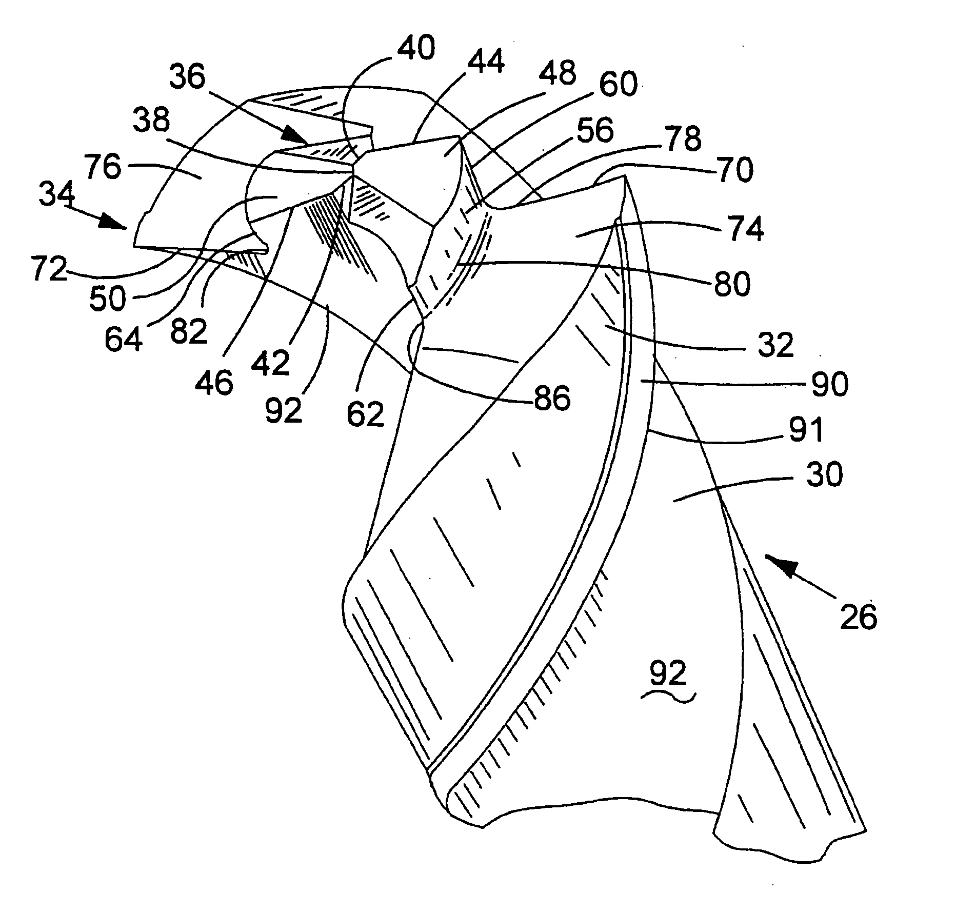
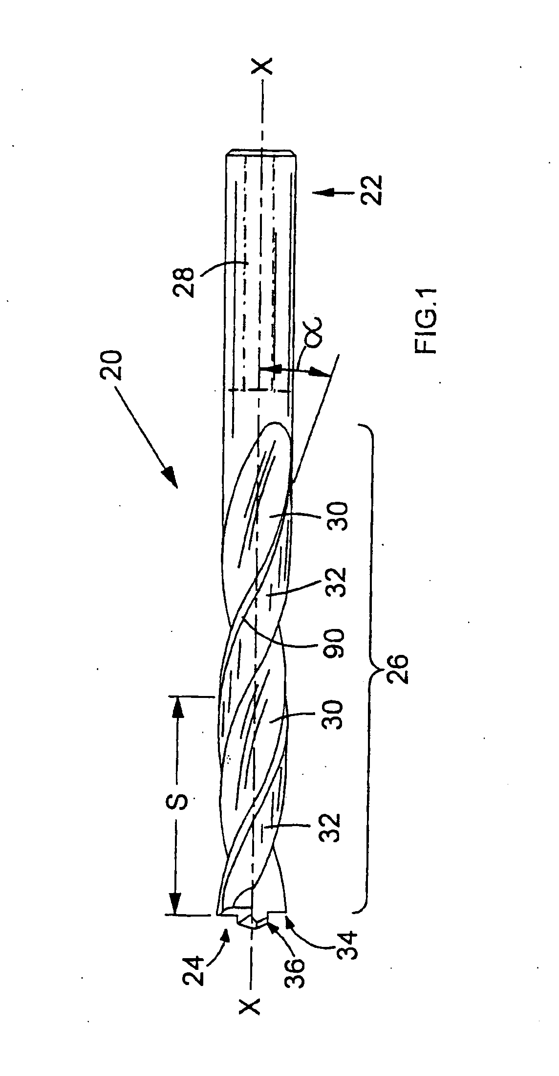
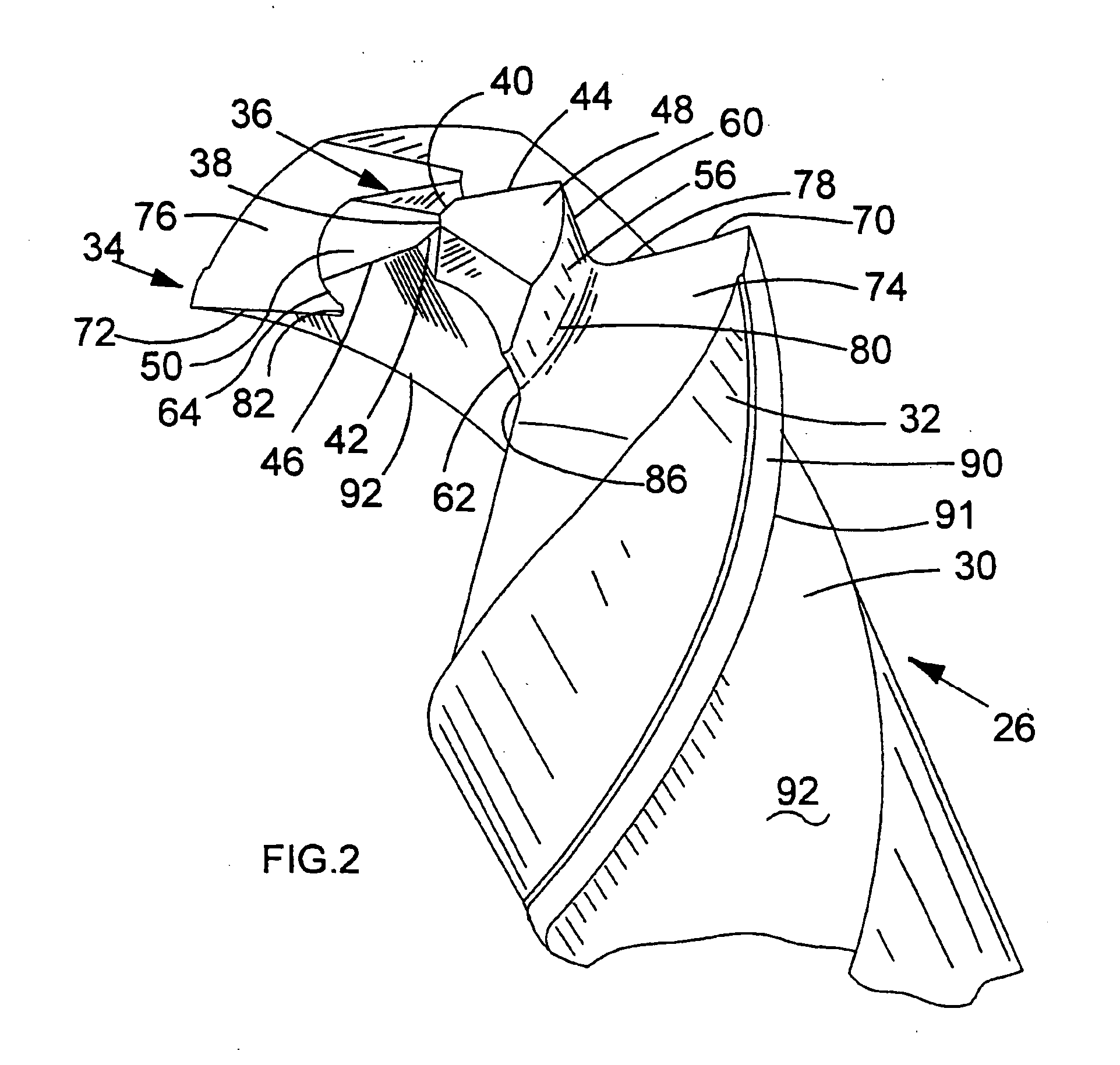
[0027] Referring to FIG. 1, a drill bit 20 is shown for cutting a variety of material such as metal, wood, plastics, plastics, piping and tubing. The drill bit 20 has a longitudinal axis X-X and is manufactured from high-speed steel. The drill bit 20 has a shank end 22, a working end 24 and a fluted section 26 interposed between the shank end 22 and the working end 24. The shank end 22 includes a substantially cylindrical shank 28 that extends from one end of the drill bit 20 to the fluted section 26. The shank 28 connects to a tool holder (not shown) of a power tool. Optionally, the shank 28 may have a plurality of axially parallel flat chamfers arranged equi-angularly around its circumference (as shown in phantom in FIGS. 1 and 8) to improve the connection with a tool holder of a power tool. The fluted section 26 ...


PUM

PropertyMeasurementUnit
Fractionaaaaaaaaaa
Fractionaaaaaaaaaa
Fractionaaaaaaaaaa

Abstract

An elongate drill bit (20) with a longitudinal axis (X-X) has a shank (28), a working end (24), and a fluted section (26) between the shank and the working end. The shank, the working end and the fluted section are all formed integrally in the drill bit. The working end has an outer cutting portion (34) and a central pilot tip (36) which extends axially ahead of the outer cutting portion. The pilot tip is formed with at least one pair of minor cutting edges (40, 42; 44, 46) arranged on opposite sides of the axis. The outer cutting portion is formed with a pair of major cutting edges (70, 72) arranged on opposite sides of the axis. The outer cutting portion has a major diameter (D) defined by the pair of major cutting edges. The pilot tip has a minor diameter (d) defined by the at least one pair of minor cutting edges. The fluted section has a pair of helical lands (32) each with a respective inner surface (92) extending axially rearward from one of the major cutting edges and from one of the minor cutting edges. The helical lands define a web (94). Each helical land defines a respective helical flute (30). The helical lands have a pitch (S) and the web has a web thickness (K) at the pilot tip such that the ratio of the pitch to the major diameter (S:D) falls within a range of about 380% to about 410%. Also, the ratio of the minor diameter to the web thickness at the pilot tip (d:K) falls within a range of about 220% to about 380%.

Description

CROSS-REFERENCE TO RELATED APPLICATIONS [0001] This application claims priority to United Kingdom Patent Application Nos. GB 0320962.4 filed Sep. 8, 2003 and 0324996.8 filed Oct. 27, 2003, which applications are herein expressly incorporated by reference. FIELD OF THE INVENTION [0002] The present invention relates to a drill bit for cutting accurately formed round holes of uniform diameter through wood, metal and plastics. BACKGROUND OF THE INVENTION [0003] One of the most commonly used drill bits to drill through metal is a twist drill formed with a chisel edge at the working end of the drill bit. The chisel edge is formed perpendicular to the axis of the drill bit and usually extends across a small portion of the drill bit diameter. Also, the chisel edge extends equally on opposite sides of the drill bit axis. A cutting edge extends from each opposite end of the chisel edge and tapers axially rearward to the outer periphery of the drill bit diameter. In use, the chisel edge is the...

Claims


Application Information

Patent Timeline
IPC IPC(8): B23B51/00B23B51/02
CPCB23B51/02B23B2251/04B23B2251/043Y10T408/9097B23B2251/404B23B2251/60Y10T408/9065B23B2251/14
Inventor WETZL, ALFONSROMPEL, MARKUS
Owner BLACK & DECKER INC
Why Eureka
Try Eureka