Cabin air quality system

a technology for air quality systems and cabins, applied in the direction of lighting and heating apparatus, heating types, separation processes, etc., can solve the problems of vocs or svocs not being removed, adsorbent damage and inactivation of certain adsorbents, cardboard or paper support damage,

Inactive Publication Date: 2005-03-10
HONEYWELL INT INC
View PDF9 Cites 70 Cited by
  • Summary
  • Abstract
  • Description
  • Claims
  • Application Information

AI Technical Summary

Benefits of technology

[0009] In one aspect of the present invention, there is provided an air quality system for removing a pollutant from an air stream, the air quality system including an interior air space, and at least one air cleaner unit in communication with the interior air space, wherein the at least one air cleaner unit provides a single flow path for the air stream. The at least one air cleaner unit comprises a first photocatalytic oxidation unit and a first adsorbent unit, and the first photocatalytic oxidation unit is located upstream or downstream from the first adsorbent unit.

Problems solved by technology

Although HEPA filters of prior art air circulatory systems remove some particulates, they do not remove gaseous or molecular pollutants such as VOCs or SVOCs.
For example, certain adsorbents may be damaged and inactivated by exposure to the UV light used for oxidizing pollutants via the photocatalytic agent.
In addition, the cardboard or paper support may also be damaged by exposure to the UV light.
Such damage to the support may result in the loss of impregnated adsorbent and / or photocatalytic agent over time.
Additionally, placing both adsorbent and photocatalytic agent on the same support limits the loading of each since they compete with each other for locations on the support.
Furthermore, putting the adsorbent and the photocatalytic agent on the same support means that both are in powder form, which limits the adsorbent capacity for unit volume and weight as compared with self-supporting woven or pleated adsorbent media.
Still further, putting adsorbent and photocatalytic agent on the same support limits flexibility in configuring an air quality system for different situations or environments.

Method used


Image

  • Cabin air quality system
  • Cabin air quality system
  • Cabin air quality system

Examples


example 1

[0091] A PCO unit comprising two parallel PC panels was constructed. Each PC panel was 20×24 inches in cross section, and the two PC panels were spaced five inches apart. The panels were coated with photocatalyst as described in commonly assigned U.S. patent application Ser. No. 10 / 345,022, filed Jan. 14, 2003, the disclosure of which is incorporated by reference herein in its entirety. Two 36 W UV lamps were positioned midway between the two PC panels. An air stream containing acetaldehyde (inlet concentrations in the range of 0.147 to 0.331 ppmw) was passed through the PCO unit. The air temperature of the air stream was in the range of 79-85° F., and the relative humidity was in the range of 35-48%.

[0092] Sampling ports were arranged so as to allow sampling of the air stream at both the inlet and the outlet of the PCO unit. The air so sampled was pumped to the injection port of a gas chromatograph for analysis of acetaldehyde concentration. Samples were taken from the outlet both...

example 2

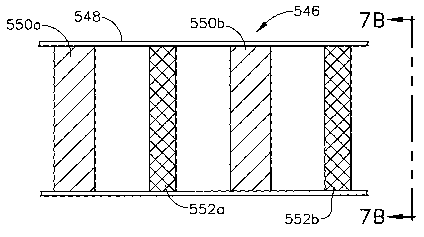
[0093] A PCO unit comprising five parallel PC panels was constructed. Each panel was 20×24 inches in cross section, and the PC panels were spaced three inches apart. Two 36 W UV lamps were mounted between each successive pair of PC panels for a total of eight UV lamps. An air stream contaminated with low concentrations of acetaldehyde was passed through the PCO unit. The air temperature was 85° F., and the relative humidity was 21%. Air was sampled and analyzed by gas chromatography, essentially as described in Example 1. Table 3 reports average values of several measurements for each condition. The % removal of acetaldehyde from the air stream was calculated by comparing the “lights OFF” and “lights ON” conditions.

TABLE 3Removal of Acetaldehyde from an Air Stream via a PCO Unit havingFive PC panelsOutlet conc.Outlet conc.lights OFF,lights ON,(ppmw)(ppmw)% Removal+ / −0.7320.64511.86%1.82%0.5450.45915.75%3.25%0.3650.32112.13%1.88%0.2910.22223.70%11.67%0.2050.12140.97%5.74%0.1960.165...

example 3

[0095]FIG. 10 shows the results of a number of experiments performed using the PCO units described in Examples 1 and 2. The flow rate of the air stream for these experiments was 500 cfm. For each experiment, the % removal of acetaldehyde from the air stream was normalized by the number of PC panels to express the data as fractional removal / panel. The equation used for this normalization was: Fractional⁢ ⁢removal⁢ / ⁢panel=1-ⅇ(ln⁡(1-R)P),

[0096] It is apparent from FIG. 10 that fractional removal per panel tends to be higher at lower concentrations of acetaldehyde, and lower at higher concentrations. A PCO unit of the type described in Examples 1 and 2 will therefore function well with a steady low concentration of pollutant in the feed air stream. Such a feed may be experienced, for example, when an upstream adsorbent unit initially adsorbs any pulse(s) of pollutant, and subsequently desorbs the pollutant to the PCO unit at a manageable rate, generally as described hereinabove.


PUM

PropertyMeasurementUnit
temperatureaaaaaaaaaa
constant temperatureaaaaaaaaaa
porosityaaaaaaaaaa

Abstract

An air quality system comprising at least one air cleaner unit in communication with an interior air space. In one embodiment, an air quality system for an aircraft comprises a first set of air cleaner units in communication with a lower plenum of the aircraft recirculation system and a second set of air cleaner units in communication with an upper plenum of the aircraft recirculation system. Each air cleaner unit comprises at least one adsorbent unit in combination with at least one photocatalytic oxidation unit. In one embodiment, an air cleaner unit comprises a relatively weak adsorbent material upstream from a photocatalytic oxidation unit, and a relatively strong adsorbent material downstream from the photocatalytic oxidation unit. Methods for removing a pollutant from an air stream and for making an air cleaner unit are also disclosed.

Description

BACKGROUND OF THE INVENTION [0001] The present invention generally relates to an air cleaner unit and to an air quality system for providing cleansed air to an interior air space. The present invention also relates to methods for removing a pollutant from an air stream via an air cleaner unit or an air quality system. [0002] There is increasing interest in supplying clean, pollution-free air to interior air spaces, such as onboard commercial aircraft. To provide cleansed air to an interior air space, such as an aircraft cabin, it may be desirable to remove pollutants such as dust or other particulates, as well as volatile- or semi-volatile organic compounds (VOCs, SVOCs) from an air stream to be fed to the interior air space. It may further be desirable to remove, or inactivate (kill), microorganisms (e.g., various bacteria), and viruses, which may be human pathogens. In the case of a vehicle, such as an aircraft, such objectives must be accomplished by an air quality system within ...

Claims


Application Information

Patent Timeline
Patent Type & Authority Applications(United States)
IPC IPC(8): A61L9/16A61L9/20B01D53/04B01D53/86B64D13/00
CPCA61L9/16A61L9/20B01D53/04B01D53/0446B01D53/8668B01D2253/102B01D2253/308B01D2255/802B01D2257/708B01D2259/41B01D2259/4508B01D2259/4575B64D13/00B64D2013/0651F24F8/167
Inventor YATES, STEPHENFUENTES, FELIPEMICHALAKOS, PETERCHANG, CHINKRAFTHEFER, BRIANKAISER, MARK
Owner HONEYWELL INT INC
Why Eureka
Try Eureka