
System for controlling nozzle touch force

a technology of touch force and nozzle, which is applied in the field of injection molding machines, can solve the problems of further dropping the quality of the molded article, and reducing the life of the metal mold, so as to achieve the effect of simple structure and easy maintenan

Active Publication Date: 2005-03-10
FANUC LTD
View PDF2 Cites 6 Cited by
  • Summary
  • Abstract
  • Description
  • Claims
  • Application Information

AI Technical Summary

Benefits of technology

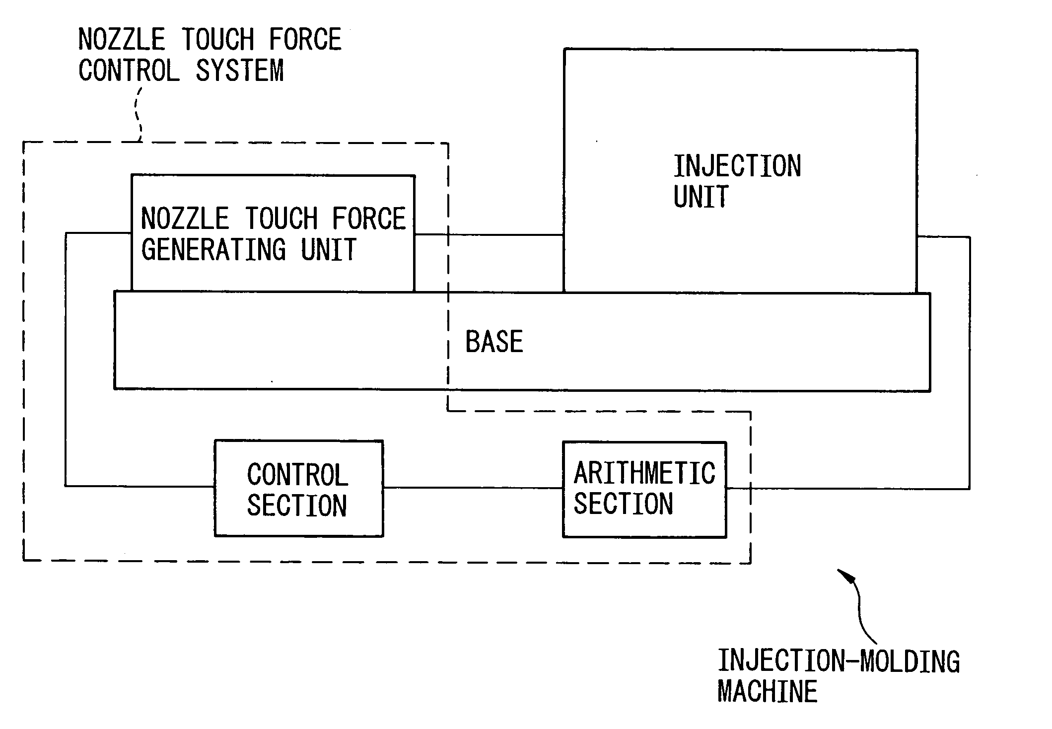
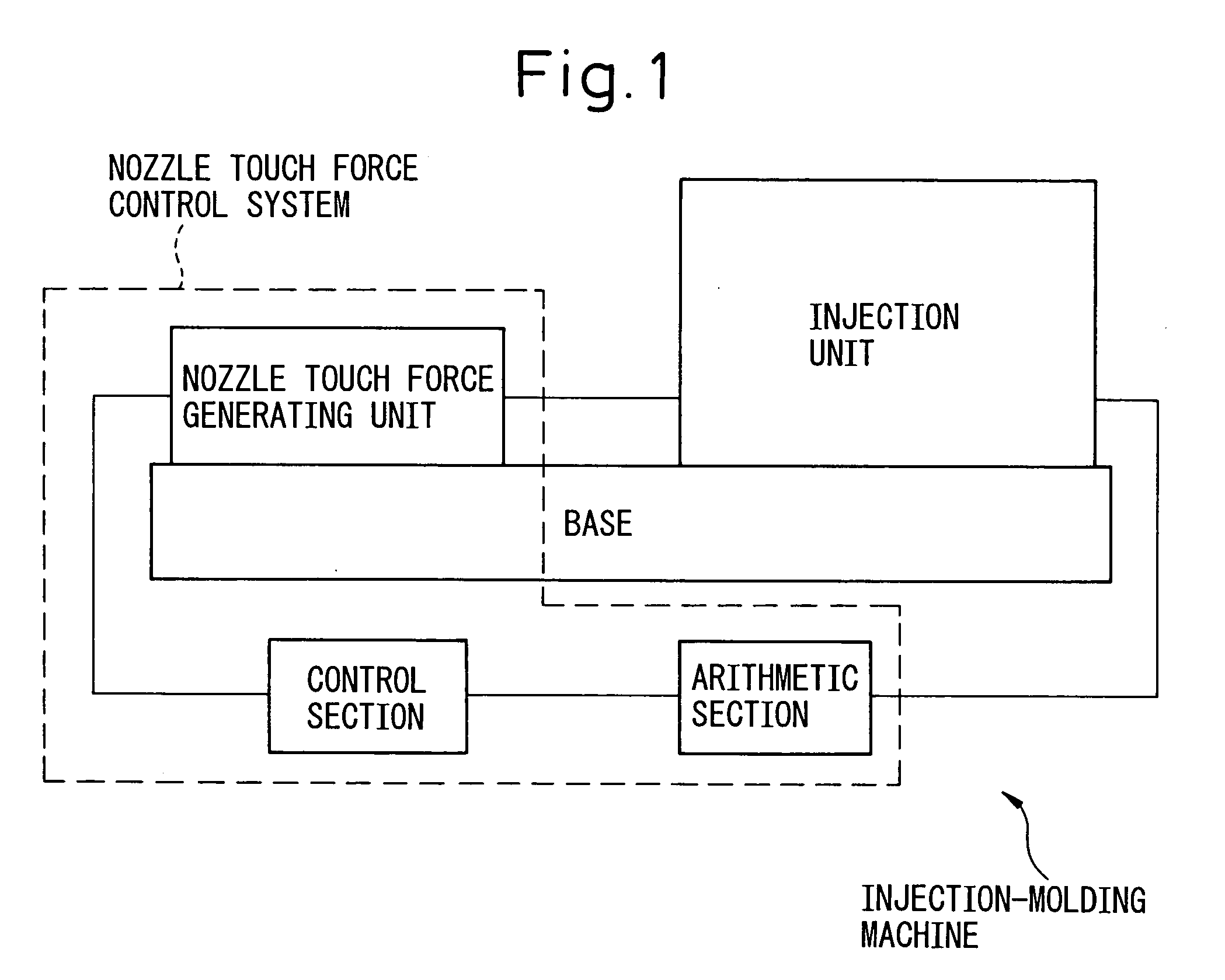
[0012] It is therefore an object of the present invention to provide a system for controlling the nozzle touch force, which is simple in structure and is capable of easily maintaining a predetermined nozzle touch force.
[0016] Alternatively, the nozzle touch force generating unit includes an electric motor the torque of which can be controlled to generate a nozzle touch force relying upon the output torque of the electric motor, and the control unit increases or decreases a value of the output torque of the motor by a correcting torque value calculated by multiplying the acceleration of the moving part of the injection unit by the preset value, to so control the electric motor as to produce a predetermined nozzle touch force.

Problems solved by technology

When pushed with a large nozzle touch force, however, the metal mold deflects and / or a parallel relationship of the mold is not maintained, giving rise to problems with regard to a drop in the quality of the molded article and a decrease in the life of the metal mold.
As shown in FIG. 9b, also, the nozzle touch force increases due to the force of inertia at the time of deceleration in the injection speed, causing a further decrease in the life of the metal mold.

Method used


Image

  • System for controlling nozzle touch force
  • System for controlling nozzle touch force
  • System for controlling nozzle touch force

Examples


first embodiment

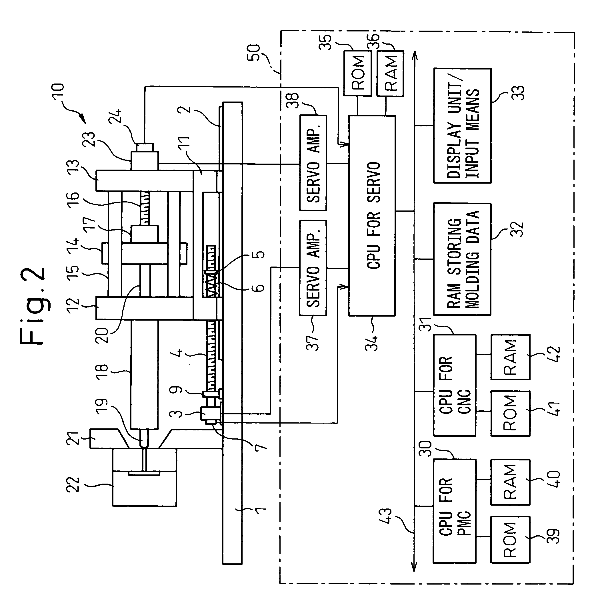
[0033]FIG. 2 is a diagram illustrating a major portion according to the present invention. As shown, on a rail 2 provided on the base 1 of the injection-molding machine, there is arranged a unit base 11 that constitutes a portion of the injection unit 10 so as to move back and forth. An injection mechanism is mounted on the unit base 11 so as to be turned for the replacement and maintenance of the injection screw. The injection mechanism includes a front plate 12, a rear plate 13, and a pusher plate 14 guided by a plurality of guide bars 15 coupling the front plate 12 and the rear plate 13 together, and a nut 17 is secured to the pusher plate 14 so as to be screwed onto a ball screw 16 for injection. The pusher plate 14 rotatably holds an injection screw 20 that is inserted in the heating cylinder 18. A nozzle 19 is provided at an end of the heating cylinder 18, and is allowed to come in contact with, or separate away from, a metal mold 22 mounted on a stationary platen 21. A servo ...

second embodiment

[0054] In the second embodiment, the CPU 30 for PMC sends a torque instruction To corresponding to a preset nozzle touch force to the motor 3′ of which the torque can be controlled through the CPU 34 for servo and the amplifier. Being driven by the electric motor 3′, the ball screw rotates, the injection unit moves forward due to the nut screwed onto the ball screw, and the nozzle 19 comes in contact with the metal mold 22. When the injection unit 10 is no longer moved, the electric motor 3′ produces the torque T0 as instructed, and the nozzle touch force is maintained at the preset nozzle touch force.

[0055]FIG. 5 is a flowchart of a nozzle touch force control processing executed in the injection / pressure-maintaining step at regular intervals according to the second embodiment of the present invention. In the injection / pressure-maintaining step, the CPU 30 for PMC executes the same processings as those of the steps 100 to 102 of the first embodiment, reads the speed V of injection, ...


PUM

PropertyMeasurementUnit
forceaaaaaaaaaa
accelerationaaaaaaaaaa
speedaaaaaaaaaa

Abstract

A system for controlling nozzle touch force, which is capable of maintaining the touch force relying upon a simple constitution. An electric motor moves the injection unit forward via a spring to bring a nozzle into contact with a metal mold. Further, the spring is compressed to impart a preset nozzle touch force. In the injection / pressure-maintaining step, the screw is driven, and a position / speed detector provided on a servo motor for injecting the resin detects the injection speed at regular intervals. A force produced by the force of inertia of the moving portions such as the injection screw and the pusher plate that move due to the injection operation, is found from the acceleration that is found from the injection speed. The amount of compression of the spring is controlled by varying the rotational position of the motor by an amount corresponding to the force that is found to maintain the nozzle touch force constant. Since the nozzle touch force is maintained constant, no resin leaks and an excess of nozzle touch force is not produced, either.

Description

BACKGROUND OF THE INVENTION [0001] 1. Field of the Invention [0002] The present invention relates to an injection-molding machine and, particularly, to a system for controlling the nozzle touch force of the injection-molding machine. [0003] 2. Description of the Related Art [0004] In a nozzle touch mechanism which moves an injection unit as a whole to bring it into contact with a metal mold, the injection unit mounted on a base so as to move back and forth is driven by a nozzle touch force generating device to bring the nozzle of the injection unit into contact with the metal mold. A known nozzle touch force generating device utilizes a hydraulic cylinder or a spring force expanded by the force of a motor to hold the nozzle in contact with to the metal mold (see Japanese Examined Patent Publication (Kokoku) No. 6-17038) [0005] There is further known a nozzle touch mechanism which pushes the nozzle onto the metal mold with a predetermined pressure by using a hydraulic pressure. The n...

Claims


Application Information

Patent Timeline
Patent Type & Authority Applications(United States)
IPC IPC(8): B29C45/17B29C45/20B29C45/76
CPCB29C45/1777B29C2945/76939B29C2945/76006B29C2945/76083B29C2945/7611B29C2945/76113B29C2945/76187B29C2945/76307B29C2945/76381B29C2945/76498B29C2945/76505B29C2945/76511B29C2945/76525B29C2945/76568B29C2945/76595B29C2945/76695B29C2945/76785B29C2945/76933B29C45/76
Inventor NAGAYA, MOTOHIROKAWASAKI, TATSUYAHASHIMOTO, NOBUAKI
Owner FANUC LTD
Learn More