Turf image marker

a technology of image marker and vehicle, applied in the direction of vehicle position/course/altitude control, process and machine control, instruments, etc., can solve the problem of typical time-consuming, and achieve the effect of reducing power requirements and no time wasted in turning the vehicl

Inactive Publication Date: 2005-03-10
MCMURTRY
View PDF19 Cites 82 Cited by
  • Summary
  • Abstract
  • Description
  • Claims
  • Application Information

AI Technical Summary

Benefits of technology

[0020] The first of the last three methods is the most efficient as no time is wasted in turning the vehicle and therefore the power requirements are also reduced.

Problems solved by technology

This typically takes considerable time especially if one playing surface is used for two or more sports.

Method used


Image

  • Turf image marker
  • Turf image marker
  • Turf image marker

Examples


Embodiment Construction

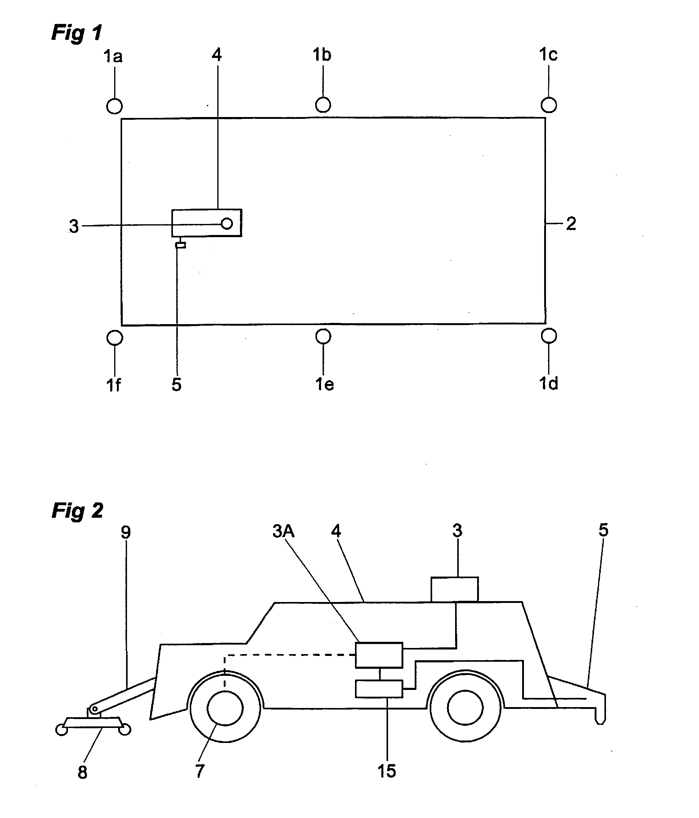
[0032]FIG. 1 is a plan view of a turfed sports field 2. An autonomous ground maintenance vehicle in the form of a mower marker vehicle 4 is able to move around the sports field.

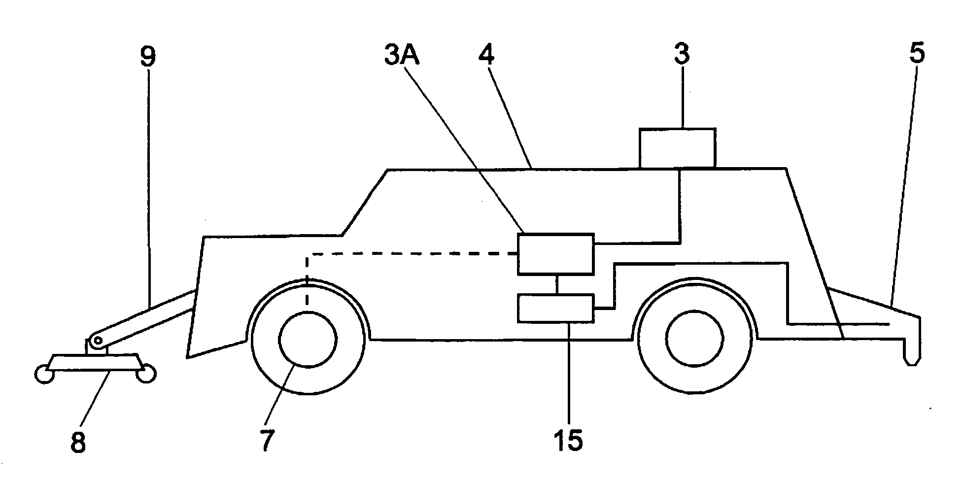
[0033]FIG. 2 shows the mower marker vehicle 4. It has maintenance equipment in the form of a grass mowing device 8 supported on the chassis 10 of the vehicle 4 by a support 9. At the opposite end of the vehicle marking means in the form of a dispensing device 5 is provided. The vehicle 4 has four wheels 6a to 6d, and an encoder 7 measures the rotation of one of the wheels 6, thereby to provide data representing the distance traveled by the vehicle 4 by means of odometry. The positional data from the detecting means 3 and the encoder 7 is input to guidance means 3A which controls the travel of the vehicle 4 and the operation of the mowing device 8.

[0034] As shown in FIG. 1 the sports field 2 is surrounded by fixed reference markers 1a, 1b, 1c, 1d, 1e and 1f. A detecting means 3 is provided on the vehicle 4 f...


PUM


Abstract

An autonomous ground maintenance vehicle is provided with maintenance equipment for performing a ground maintenance operation, such as mowing and storing grass, a marking device that includes a delivery structure for applying a marking material to the ground, a guidance mechanism for guiding the ground maintenance vehicle, and a position sensor for determining the position of the vehicle. The marking device is controlled in response to the position of the vehicle according to the position sensor.

Description

CROSS-REFERENCE TO RELATED APPLICATIONS [0001] This application is a continuation of International Application No. PCT / GB03 / 00347, filed Jan. 28, 2003, which claims priority from U.K. Patent Application No. 0207107.4, filed Mar. 26, 2002. The disclosures of both applications are incorporated herein by reference.BACKGROUND OF THE INVENTION [0002] This invention relates to an autonomous ground maintenance vehicle. [0003] Conventionally, advertisements and logos have been marked on sports fields using wet paints or powders dispensed either with a walk behind sprayer or such like or a paint brush. Generally, line marking devices and other ground maintenance machines are independent vehicles used at different stages of the maintenance process by the groundsman or user. Usually the turfed area of a playing surface is cut, aerated or brushed with a machine adapted specifically for the job before the lines or advertising logo are put on the surface. Typically the lines defining the sports a...

Claims


Application Information

Patent Timeline
Patent Type & Authority Applications(United States)
IPC IPC(8): A63C19/00
CPCA63C19/00G05D1/0234G05D1/0272G05D2201/0208
Inventor MCMURTRY, RICHARDMCMURTRY, BEN
Owner MCMURTRY
Why Eureka
Try Eureka