Spark generating apparatus having strain gage cylinder pressure measurement feature

a technology of pressure measurement and spark generating apparatus, which is applied in the direction of work measurement, measurement devices, instruments, etc., can solve the problems of large and costly production of coils and/or spark plugs, increase cost, and increase the cost of production

Inactive Publication Date: 2005-03-17
DELPHI TECH INC
View PDF15 Cites 11 Cited by
  • Summary
  • Abstract
  • Description
  • Claims
  • Application Information

AI Technical Summary

Benefits of technology

[0008] An apparatus according to the present invention includes a central electrode, an insulator, a conductive shell, a second electrode, and a strain gage. The central electrode has a main axis and a first end configured for connection to a relatively high voltage source. The insulator is located outwardly of the central electrode. The central electrode further includes a second, exposed end opposite the first end. The conductive shell is located outwardly of and surrounds the insulator. The second electrode is spaced apart from the exposed end of the central electrode to define a spark gap therebetween. The second electrode is electrically connected to the shell. According to the invention, a strain gage is affixed to the shell. In operation, the shell becomes a pressure member wherein the stress applied to the shell during, for example, piston strokes, will flex the shell. The strain gage converts the deformation to a resistance change measurable by way of, for example, a bridge circuit, in one embodiment.
[0009] In an alternate embodiment, a spark generating assembly is provided that integrates an ignition coil with a spark plug configured to include a strain gage as described above. In still further embodiments, the strain gage is incorporated (i.e., applied to) into one or more fuel injectors of a Direct Gasoline Injection (DGI) engine, the glow plugs in a diesel engine, or any other component protruding into the combustion chamber. Additionally, the strain gage can be incorporated onto a cylinder head, head bolt, engine block, and / or main bearing cap or bolt. Moving parts could also be the subject of (destination for) the strain gage including the piston, connecting rod, crankshaft, and valve train components or the like.
[0010] A method of making a spark generating apparatus according to the invention is also presented.

Problems solved by technology

However, such conventional ignition coils and / or spark plugs do not generally incorporate a pressure sensor and often are large and costly to produce.
This increases cost, and subjects the resulting signal to noise due to environmental factors (e.g., magnetic and electrical noise in an automotive environment).
As with the Meyer device, additional components such as a magnet are needed, which increase cost and complexity.
Additionally, piezoelectric devices have been used in a laboratory environment but are not feasible for mass production.

Method used


Image

  • Spark generating apparatus having strain gage cylinder pressure measurement feature
  • Spark generating apparatus having strain gage cylinder pressure measurement feature
  • Spark generating apparatus having strain gage cylinder pressure measurement feature

Examples


Embodiment Construction

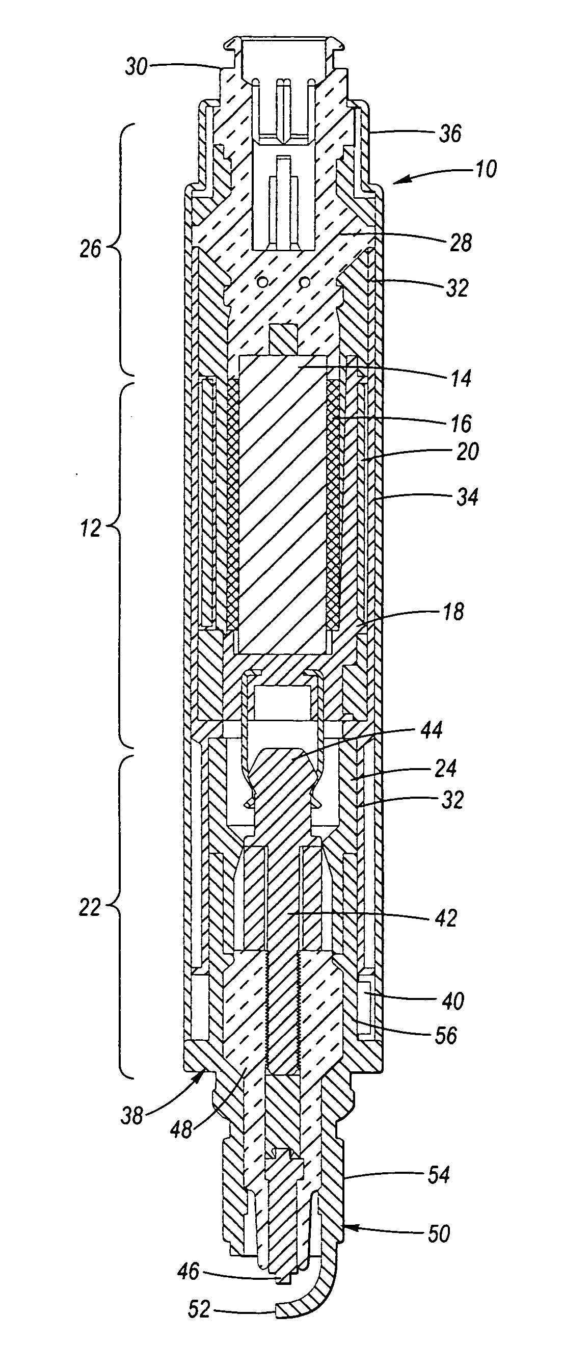
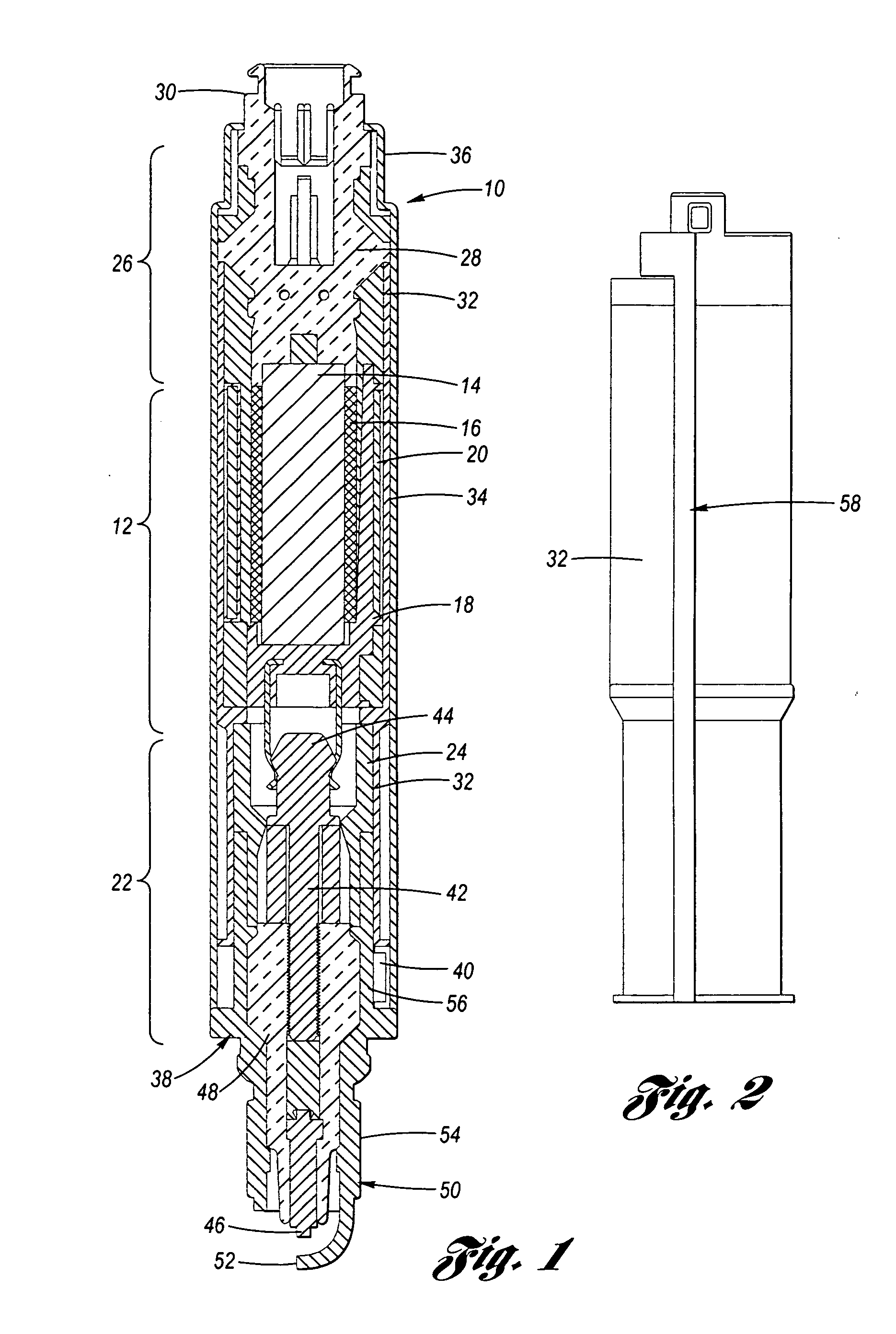
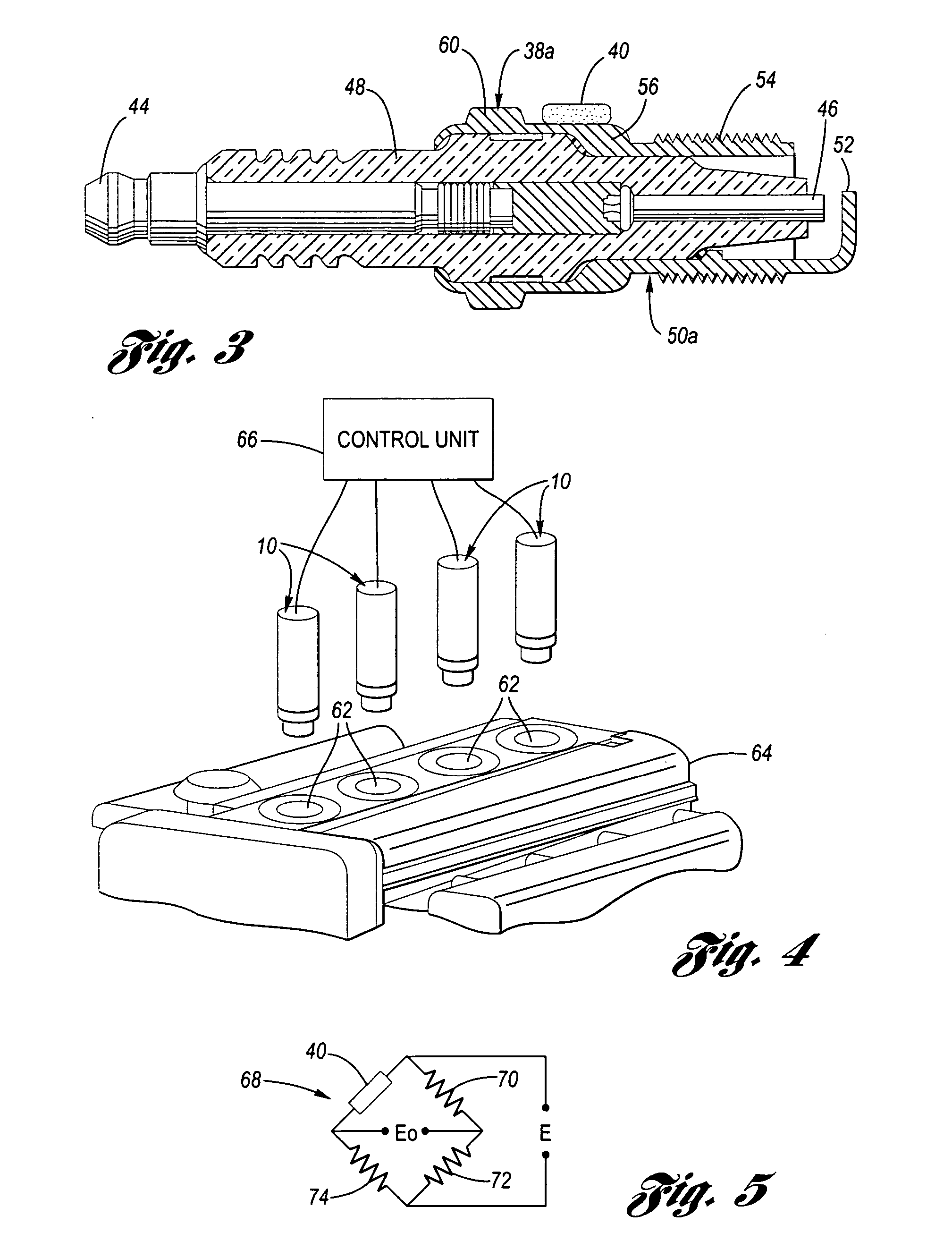
[0017] Referring now to the drawings wherein like reference numerals are used to identify identical components in the various views, FIG. 1 shows a preferred embodiment of an integrated ignition coil, spark plug and pressure sensor assembly 10 in accordance with the present invention. The assembly 10 is adapted for installation to a conventional internal combustion engine 64 through a spark plug shell and in threaded engagement with a spark plug opening 62 into a combustion cylinder. This arrangement is best shown in FIG. 4.

[0018]FIG. 1 illustrates assembly 10 having a transformer portion 12 comprising a core 14, a primary coil 16, a secondary spool 18 and a secondary coil 20, a connection portion 22 comprising a high-voltage boot 24, a control circuit portion 26 comprising an assembled connector portion 28 and a circuit interface portion 30, a coil case 32, an outer housing or shield 34 comprising a fastening head 36, a spark plug assembly 38, and a pressure sensor assembly compri...


PUM

PropertyMeasurementUnit
pressureaaaaaaaaaa
voltageaaaaaaaaaa
conductiveaaaaaaaaaa

Abstract

An ignition coil, spark plug, and pressure sensor for an internal combustion engine are, in a preferred embodiment, integrated into a single assembly and mounted directly on a plug hole of an internal combustion engine. A hard spark plug shell serves as a pressure member and on which a strain gage is affixed. Changes in the pressure in the combustion chamber deform the shell, causing a corresponding change in the resistance of the strain gage. A bridge circuit or the like is used to measure the resistance change thereby providing a direct indication of cylinder pressure.

Description

TECHNICAL FIELD [0001] The present invention relates to a spark generating apparatus with a pressure sensor. BACKGROUND OF THE INVENTION [0002] An ignition coil for an internal combustion engine that is installed directly on an engine and that is directly coupled with spark plugs is known. However, such conventional ignition coils and / or spark plugs do not generally incorporate a pressure sensor and often are large and costly to produce. A pressure sensor mounted on a spark plug is known as disclosed in U.S. Pat. No. 5,672,812 to Meyer. [0003] Meyer discloses a magnetostrictive pressure sensor device attached to a spark plug shell. The disclosed approach, however, requires a magnetized spark plug shell. This increases cost, and subjects the resulting signal to noise due to environmental factors (e.g., magnetic and electrical noise in an automotive environment). [0004] U.S. Pat. No. 6,119,667 to Boyer et al. disclose an integrated spark plug / ignition coil with a pressure sensor for a...

Claims


Application Information

Patent Timeline
Patent Type & Authority Applications(United States)
IPC IPC(8): G01L23/18G01L23/22
CPCG01L23/22G01L23/18
Inventor KIESS, RONALD J.NOEL, ROBERT A.WRIGHT, JAMES TORDTBOYER, JAMES ALVABELL, MATTHEW W.
Owner DELPHI TECH INC
Why Eureka
Try Eureka