Thermoelectric energy conversion unit and tunnel-type furnace therewith

a technology of thermal energy conversion unit and tunnel furnace, which is applied in the direction of furnaces, generators/motors, lighting and heating apparatus, etc., can solve the problems of low output density of direct generation system, low energy conversion efficiency, and heat loss, and achieve long-term stable performance, good thermal efficiency, and facilitate maintenance

Inactive Publication Date: 2005-03-17
HITACHI POWDERED METALS COMPANY +1
View PDF9 Cites 50 Cited by
  • Summary
  • Abstract
  • Description
  • Claims
  • Application Information

AI Technical Summary

Benefits of technology

[0012] According to the tunnel-type furnace of the present invention, for example, bricks, etc., are provided to the heating zone so that the heating zone is thermally insulated, and a generation portion is provided between the heating zone and the cooling zone, whereby the thermoelectric conversion module can have good thermal efficiency. Since the above thermoelectric conversion module is used in the tunnel-type furnace of the present invention, for example, the above thermoelectric conversion module can be provided to the outer face of the tunnel-type furnace, and the tunnel-type furnace thereby facilitates the maintenance thereof. In the tunnel-type furnace of the present invention, the thermoelectric conversion modules can be provided

Problems solved by technology

However, the direct generation systems have low output density and low energy conversion efficiency.
However, in the technique in the above Japanese Unexamined Patent Application Publication No. 2002-171776, when a thermoelectric conversion module is provided in the temperature raising zone or the heating zone, heat loss occurs due to a cooling device cooling the thermoelectric conversion module, and good thermal efficiency cannot be obtained overall.
In the above technique, since the thermoelectric conversion m

Method used


Image

  • Thermoelectric energy conversion unit and tunnel-type furnace therewith
  • Thermoelectric energy conversion unit and tunnel-type furnace therewith
  • Thermoelectric energy conversion unit and tunnel-type furnace therewith

Examples


Embodiment Construction

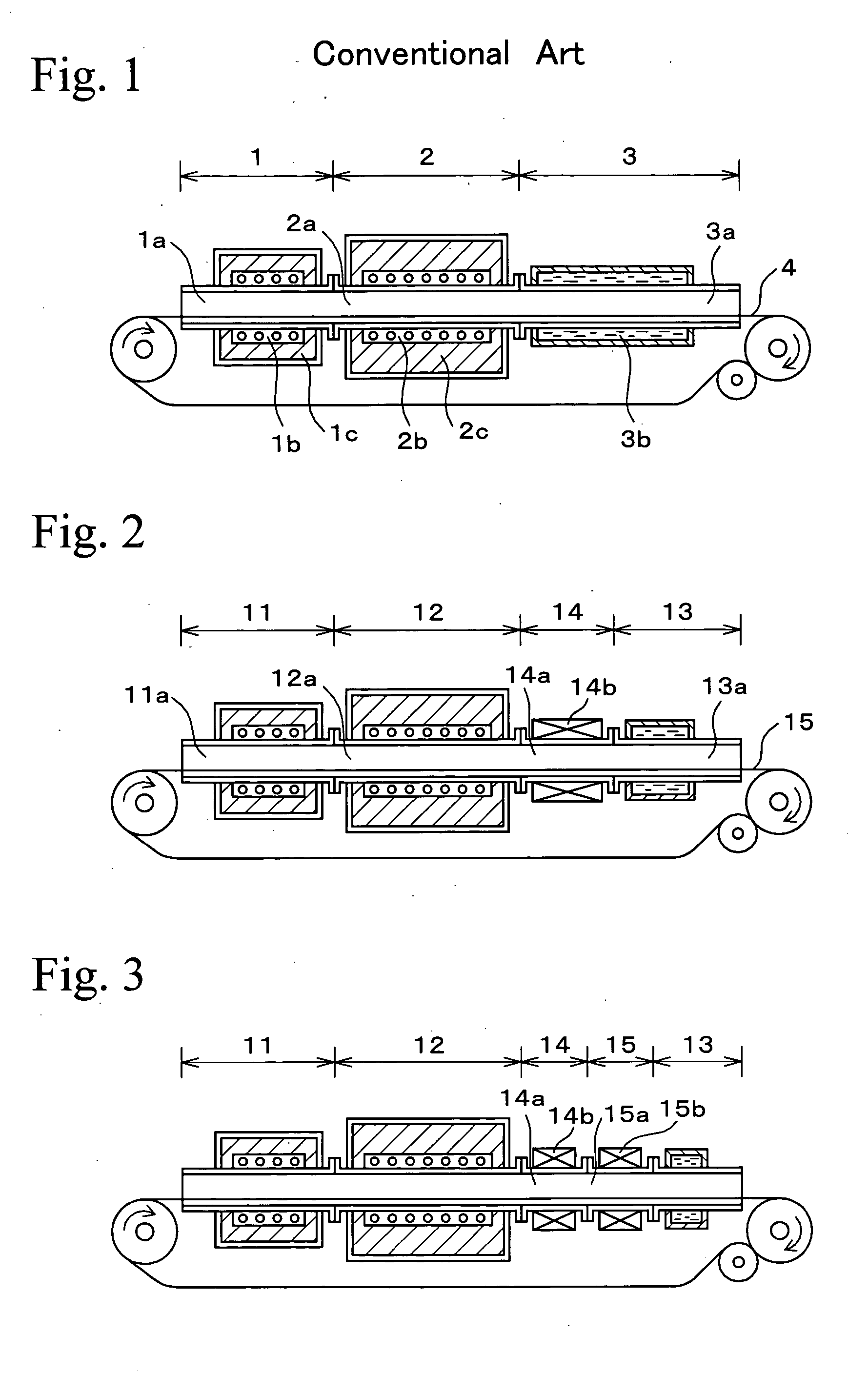
[0030] One embodiment of the present invention will be described hereinafter with reference to the Figures. FIG. 1 is a cross sectional view showing a general structure of a conventional mesh belt-type furnace (tunnel-type furnace). The furnace shown in FIG. 1 is divided into three units, that is, a preheating zone 1, a heating zone 2, and a cooling zone 3. An inner tube 1a in the pre-heating zone 1, an inner tube 2a in the heating zone 2, and an inner tube 3a in the cooling zone 3 are joined with each other. An endless belt 4 is continuously passed through the inner tubes 1a, 2a, and 3a.

[0031] In the pre-heating zone 1, a heater 1b is mounted around the inner tube 1a, and heat resisting bricks 1c are packed around the outside of the heater 1b. In the heating zone 2, a heater 2b is mounted around the inner tube 2a, and heat resisting bricks 2c are packed around the outside of the heater 2b. In the cooling zone 3, a water jacket 3b is mounted around the inner tube 3a. The heater 1b ...


PUM


Abstract

A thermoelectric energy conversion unit includes: a thermoelectric conversion module having plural thermoelectric conversion elements disposed away from each other; a heat receiving member; a cooling member, the cooling member and the heat receiving member holding the thermoelectric conversion module; and a non-oxidizing gas charged in a space formed between the heat receiving member and the cooling member.

Description

BACKGROUND OF THE INVENTION [0001] 1. Field of the Invention [0002] The present invention relates to thermoelectric energy conversion units using the Seebeck effect which convert heat energy to electric energy, and relates to tunnel-type furnaces therewith. In particular, the present invention relates to a tunnel-type furnace which provides good thermal efficiency, facilitates the maintenance thereof, and has long-term stable performance. [0003] 2. Description of the Related Art [0004] Direct generation systems generate electricity by using thermoelectric conversion modules having thermoelectric conversion elements. The direct generation systems are simply constructed and do not have moving portions, thereby having high reliability and facilitating maintenance thereof. However, the direct generation systems have low output density and low energy conversion efficiency. Due to this, research has been performed only on apparatuses for the direct generation systems for special use which...

Claims


Application Information

Patent Timeline
IPC IPC(8): F27B9/02F27B9/20F27B9/24F27B9/36F27B9/30F27D17/00H01L35/00H01L35/30H02N11/00
CPCF27B9/029F27B9/20F27B9/243H01L35/30F27D17/004H01L35/00F27B9/30H10N10/00H10N10/13
Inventor SHIKATA, HIDEOKAMBE, MITSURU
Owner HITACHI POWDERED METALS COMPANY
Why Eureka
Try Eureka