MEMS based tunable antena for wireless reception and transmission

Inactive Publication Date: 2005-03-17
INTEL CORP
View PDF5 Cites 59 Cited by
  • Summary
  • Abstract
  • Description
  • Claims
  • Application Information

AI Technical Summary

Problems solved by technology

No longer are electronic communication devices necessarily tethered by wires.
While antennas may be one of the most vital elements in a wireless system, they may be one of the most inefficient elements, typically accounting for a large portion of energy loss.
Given the size considerations, it may be difficult to have a dedicated antenna to operate

Method used


Image

  • MEMS based tunable antena for wireless reception and transmission
  • MEMS based tunable antena for wireless reception and transmission
  • MEMS based tunable antena for wireless reception and transmission

Examples


Embodiment Construction

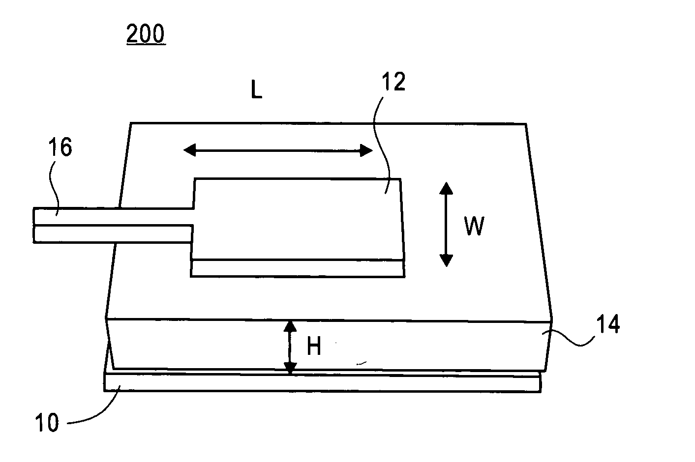
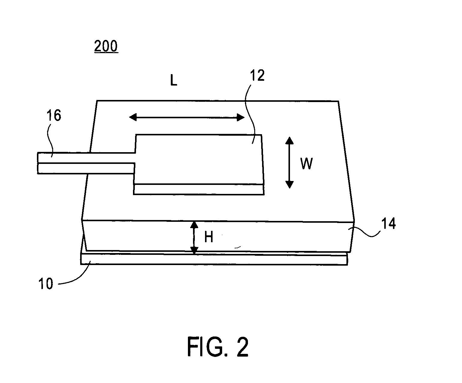
[0011] Referring now to FIG. 2, there is shown a patch antenna 200 that may be used in a mobile device, such as a cellular phone. A patch antenna 200 comprises two conducting plates, 10 and 12, sandwiching a dielectric material 14, and may be built in a similar way as a parallel plate capacitor. In the case of an antenna, the bottom conducting plate 10 may be referred to as the “ground plate”, and the top conducting plate 12 may be referred to as the “patch”. The patch 12 may comprise a thin metal foil such as copper or aluminum and may be smaller than, and centered over, the ground plate 10. An antenna feed 16 may connect to one side of the patch 12. The ground plate 10, the patch 12, and feed 16 may be made of the same conducting material. The dielectric material 14 may be, for example silicon, alumina, or a printed circuit board laminate such as FR-4.

[0012] While the patch may be any shape, for simplicity of illustration it is shown as a square or rectangular. The size of the pa...


PUM


Abstract

An antenna for a wireless device may be kept dynamically tuned to a desired center frequency to compensate for detuning which may be caused by environmental influences. A sensor provides a feedback signal to a controller to select an appropriate capacitance value from a variable capacitor to tune the antenna for the wireless device. The variable capacitor may comprise a plurality of fixed capacitors and MEMS switches arranged in parallel or may comprise a variable MEMS capacitor having a fixed lower plate and a flexible upper plate.

Description

CROSS-REFERENCE TO RELATED APPLICATION [0001] This application claims priority to U.S. Provisional Application Ser. No. 60 / 502,466, filed on Sep. 11, 2003, the contents of which are herein incorporated by reference.FIELD OF THE INVENTION [0002] Embodiments of the present invention relate to antennas and, more particularly, to MEMS (micro-electromechanical systems) tunable antennas. BACKGROUND INFORMATION [0003] No longer are electronic communication devices necessarily tethered by wires. In recent times wireless communications has become a popular and often an economical and convenient method by which to communicate both analog and digital information. In particular, cellular phones and other mobile communication devices such as personal digital assistants (PDAs), palm, and lap-top computing devices connect to service providers via wireless links. [0004] Such wireless devices rely on antenna technology to radiate radio frequency (RF) signals for transmission (Tx) as well as to gathe...

Claims


Application Information

Patent Timeline
IPC IPC(8): H01Q9/04
CPCH01Q1/38H01Q9/0442H01Q9/0407H01Q1/242H04B1/3833H04M1/0202
Inventor KIPNIS, ISSYRAO, VALLURISRINIVASAN, BALAKRISHNANHAYDEN, JOE III
Owner INTEL CORP
Why Eureka
Try Eureka