Electro-optical device, method of driving the same and electronic apparatus

a technology of electro-optical devices and electronic devices, applied in static indicating devices, instruments, electroluminescent light sources, etc., to achieve the effect of smooth control of the brightness of the electro-optical devices

Active Publication Date: 2005-03-17
ELEMENT CAPITAL COMMERCIAL CO PTE LTD
View PDF12 Cites 89 Cited by
  • Summary
  • Abstract
  • Description
  • Claims
  • Application Information

AI Technical Summary

Benefits of technology

[0006] The present invention has been made to solve the above problems, and it is an object of the present invention to provide an electro-optical device that is capable of controlling more smoothly as compared with a control in every one frame and preventing a large current from flowing when switching frames in a brightness control (a peak brightness control), a method of driving the electro-optical device and an electronic apparatus.

Problems solved by technology

Accordingly, if a brightness change between frames is large in such a manner that frame image is changed from full black to full white, a large current abruptly flows when switching frames, thereby causing a noise.

Method used


Image

  • Electro-optical device, method of driving the same and electronic apparatus
  • Electro-optical device, method of driving the same and electronic apparatus
  • Electro-optical device, method of driving the same and electronic apparatus

Examples


first embodiment

[0040] (First Embodiment)

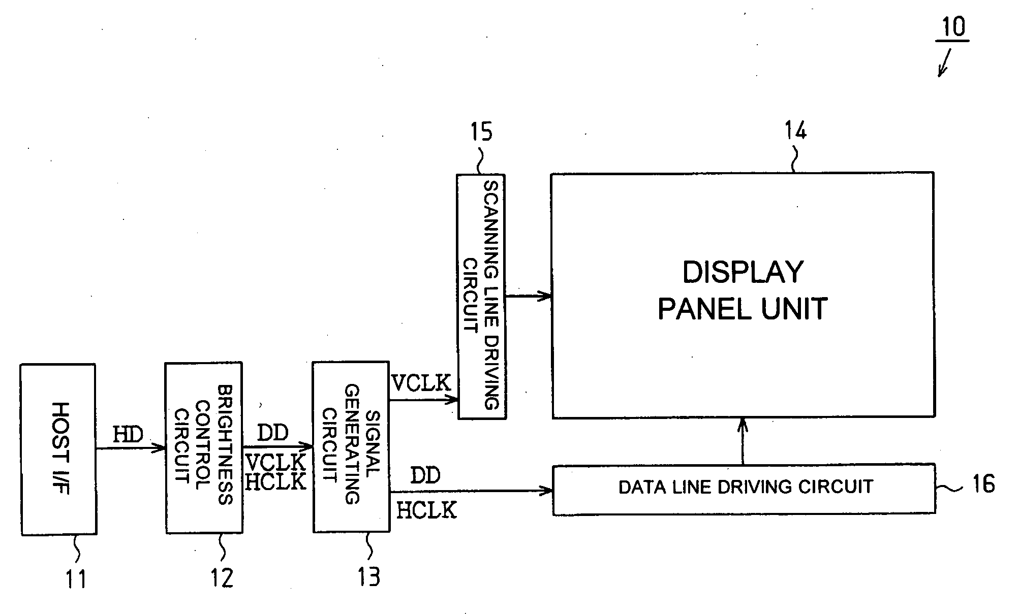
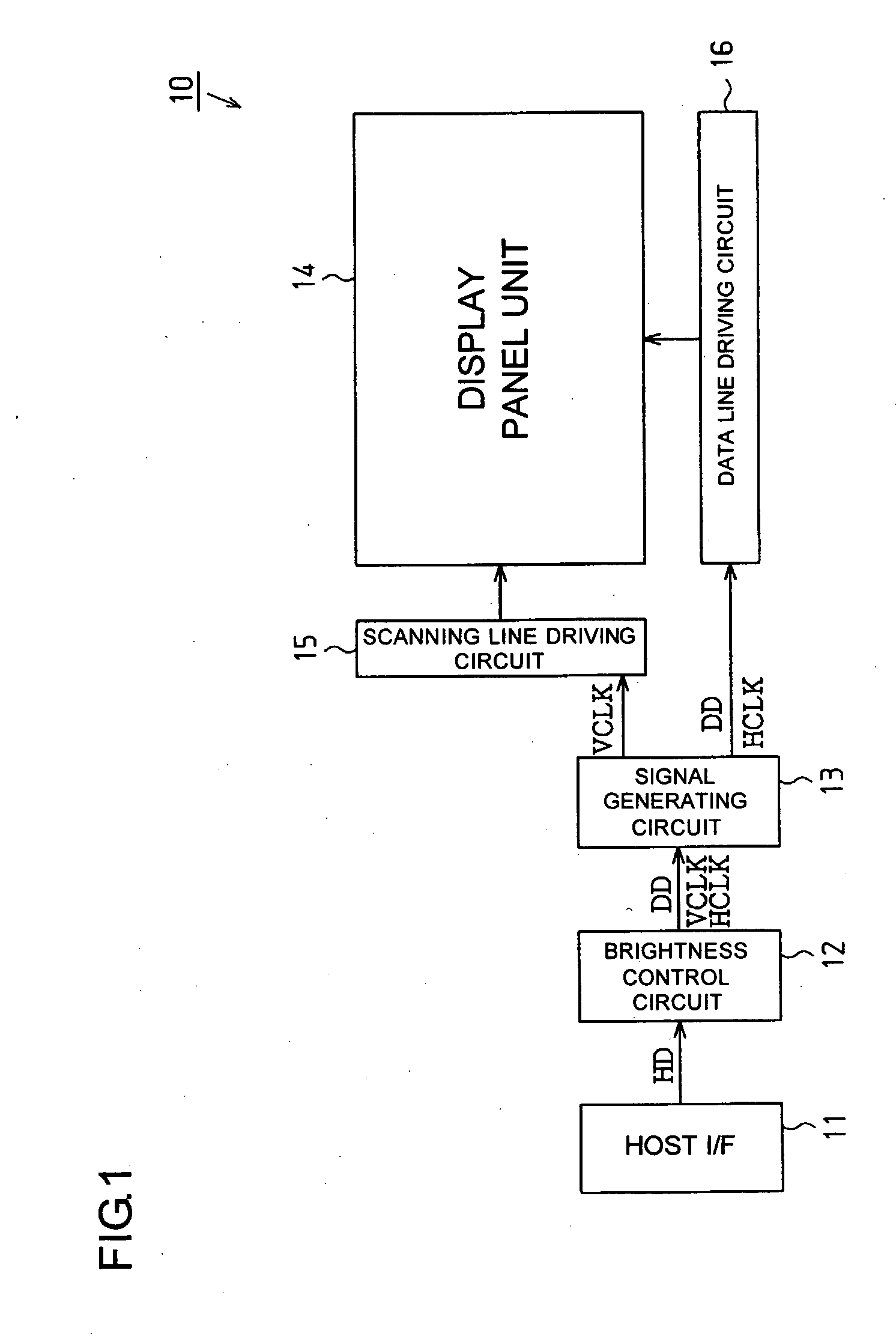
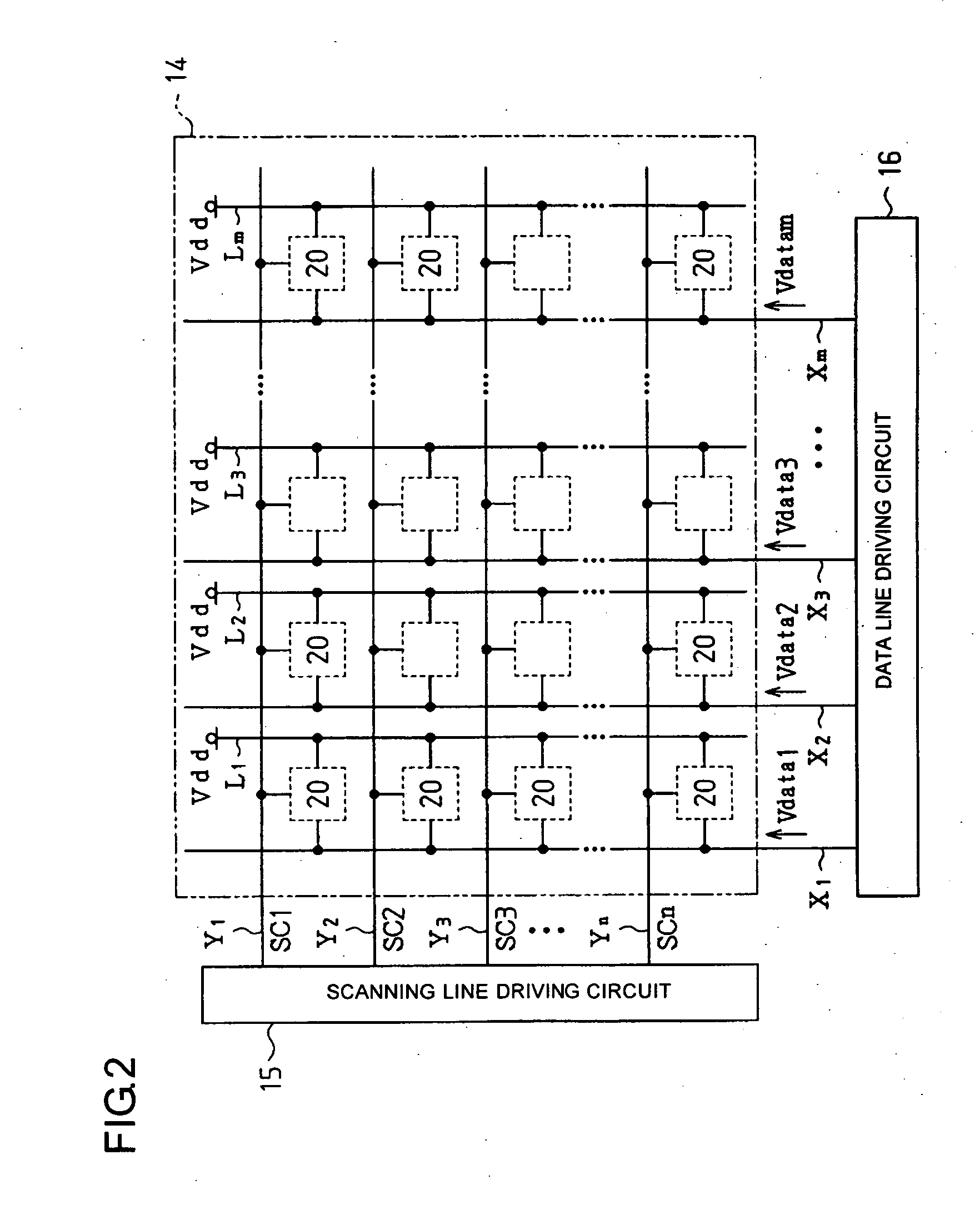
[0041] A first embodiment implementing the present invention will be now described with reference to FIGS. 1 to 5. FIG. 1 is a block circuit diagram showing an electric configuration of an organic electroluminescent display device using an organic electroluminescent element as an electro-optical device. FIG. 2 is a block circuit diagram showing a circuit configuration of a display panel unit. FIG. 3 is a circuit diagram showing an inside configuration of a pixel circuit.

[0042] The organic electroluminescent display device 10 comprises a host I / F 11, a brightness control circuit 12 as a brightness control circuit, a signal generating circuit 13, a display panel unit 14, a scanning line driving circuit 15, and a data line driving circuit 16. In addition, the organic electroluminescent display device 10 in the present embodiment has an active matrix driving method.

[0043] The brightness control circuit 12, the signal generating circuit 13, the scanning line dr...

second embodiment

[0073] (Second Embodiment)

[0074] A specific second embodiment of the present invention will be now described. The present embodiment has a feature of the grayscale data average value operation unit 33 in the brightness control circuit 12 described in the first embodiment. Accordingly, for convenience, the grayscale data average value operation unit 33 will be described with reference to FIGS. 6 to 8.

[0075] In FIG. 6, the grayscale data average value operation unit 33 comprises a line adder 41 which is a first adding circuit, a line average shift register 42 which is a shift circuit and a first shift circuit, a frame-length adder 43 which is a second adding circuit, a frame-length average shift register 44 which is a second shift circuit, a frame-length fetching timing generating circuit 45 and a ten-frame-length adder / subtracter 46. Moreover, for convenience, the number of scanning lines is 208 and the number of data lines is 528.

[0076] The line adder 41 receives grayscale data HD...

third embodiment

[0096] (Third Embodiment)

[0097] Next, an example in which an organic electroluminescent display device 10 using an organic electroluminescent element as an electro-optical device described in the first and second embodiments is applied to an electronic apparatus will be now described with reference to FIG. 9. The organic electroluminescent display device 10 can be applied to personal digital assistants such as mobile type personal computers, cellular phones, viewers, game machines, and various electronic apparatuses such as electronic books and electronic papers. Further, the organic electroluminescent display device 10 can also be applied to various electronic apparatuses such as video cameras, digital still cameras, car navigations, car stereos, driving operating panels, personal computers, printers, scanners, televisions, video players.

[0098]FIG. 9 is a perspective view showing a configuration of a mobile type personal computer. In FIG. 9, a mobile type personal computer 100 com...


PUM

PropertyMeasurementUnit
brightnessaaaaaaaaaa
grayscaleaaaaaaaaaa
brightness stateaaaaaaaaaa

Abstract

To provide a method for manufacturing an electro-optical device that is capable of controlling more smoothly brightness as compared with a control in every one frame and preventing large current from flowing when switching frames in a peak brightness control, a method of driving the same, and an electronic apparatus. A grayscale data average value operation unit 33 performs, for each line, an average value calculation of grayscale levels of images corresponding to images of an one-frame-length and outputs, based on average value for the one frame-length, mode signals M1 to M4 for brightness control in each line. A driver input data converter 34 rewrites, based on the mode signals M1 to M4 from the grayscale data average value operation unit 33, grayscale data HD for one line among grayscale data from a frame memory 31 into grayscale data DD. The driver input data converter 34 outputs grayscale data DD which is image data for the one frame-length and whose brightness is adjusted in a signal generating circuit.

Description

BACKGROUND OF THE INVENTION [0001] 1. Field of Invention [0002] The present invention relates to an electro-optical device, a method of driving the same and an electronic apparatus. [0003] 2. Description of Related Art [0004] Conventionally, electro-optical devices such as liquid crystal display devices employing liquid crystal elements, organic electroluminescent display devices employing organic electroluminescent elements, electrophoresis devices employing electrophoresis elements are known. In such electro-optical devices, when displaying images, a brightness control (a peak brightness control) is performed such that for relatively dark grayscale display, overall brightness becomes higher and for relatively bright grayscale display, overall brightness becomes lower. See, for example, Japanese Unexamined Patent Application Publication No. 6-34946. Typically, in the peak brightness control, from image data for one frame in every one frame, general brightness of the frame is obtain...

Claims


Application Information

Patent Timeline
Patent Type & Authority Applications(United States)
IPC IPC(8): G02F1/133G09G3/20G09G3/30G09G3/32G09G3/36G09G5/10G09G5/39H01L51/50H05B33/14
CPCG09G3/20G09G3/3233G09G5/39G09G2300/0842G09G2360/18G09G2320/0271G09G2320/0626G09G2330/025G09G2360/16G09G2300/0861G09G3/30G09G3/36G09G5/10
Inventor HORIUCHI, HIROSHIJO, HIROAKIKASAI, TOSHIYUKI
Owner ELEMENT CAPITAL COMMERCIAL CO PTE LTD
Why Eureka
Try Eureka