Method for forming fine concavo-convex patterns, method for producing optical diffraction structure, and method for copying optical diffraction structure

a concave pattern and pattern technology, applied in the field of fine concave pattern formation, can solve the problems of difficult to apply pressure precisely only to the predetermined fine region, difficult to copy optical diffraction structure, and high cost, and achieve the effect of taking troublesome work, high cost or high cos

Active Publication Date: 2005-03-17
DAI NIPPON PRINTING CO LTD
View PDF4 Cites 21 Cited by
  • Summary
  • Abstract
  • Description
  • Claims
  • Application Information

AI Technical Summary

Benefits of technology

Therefore, it is an object of the invention to provide a method for forming a fine concavo-convex pattern by which fine concavo-convex patterns are formed by a simple apparatus and the formation speed of the fine concavo-convex patterns is increased.
Further, according to the copying method for the optical diffraction structure of the invention, stable optical diffraction structure can be copied without costing high or taking troublesome work by beaming energy beam to the optical diffraction structure master-hologram while drawing scanning lines in one direction and then beaming energy beam in the boundary parts of each of the scanning lines.

Problems solved by technology

The pressure generating apparatus comprises, for example, a ball holding unit and a ball to be put in a cylindrical space and the space is connected to a pressure generating source via a pneumatic pipe and a solenoid valve, and thus, the apparatus is complicated and therefore becomes costly.
Further, in the case of generating pressure only in the focal point region by using a stamp, it is very difficult to apply pressure precisely only to the predetermined fine region.
Especially, in the case the formation speed of the fine concavo-convex patterns is to be increased, there is a limit to improve the formation speed only by the means of mechanically applying pressure.
With respect to the method for producing the above-mentioned optical diffraction structure in which the interference fringes for forming holographic images and diffraction lattices coexist, the exposure work has to be repeated and further development process is required and thus the production process becomes complicated and troublesome and takes a long time.
Further, the above-mentioned production method by using electron beam requires a large scale apparatus and extremely complicated computation, resulting in extremely high production cost and long time and difficulty of the production of an optical diffraction structure in a scale as large as 100 cm2 or larger.

Method used


Image

  • Method for forming fine concavo-convex patterns, method for producing optical diffraction structure, and method for copying optical diffraction structure
  • Method for forming fine concavo-convex patterns, method for producing optical diffraction structure, and method for copying optical diffraction structure
  • Method for forming fine concavo-convex patterns, method for producing optical diffraction structure, and method for copying optical diffraction structure

Examples


example 1

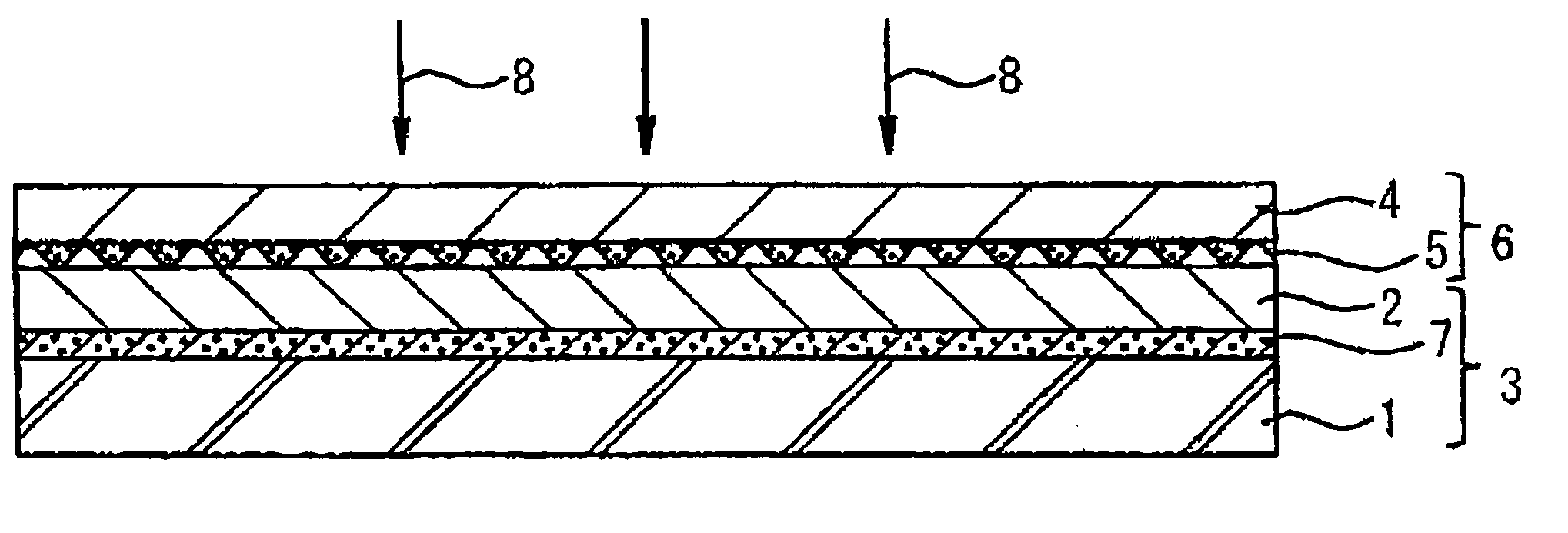
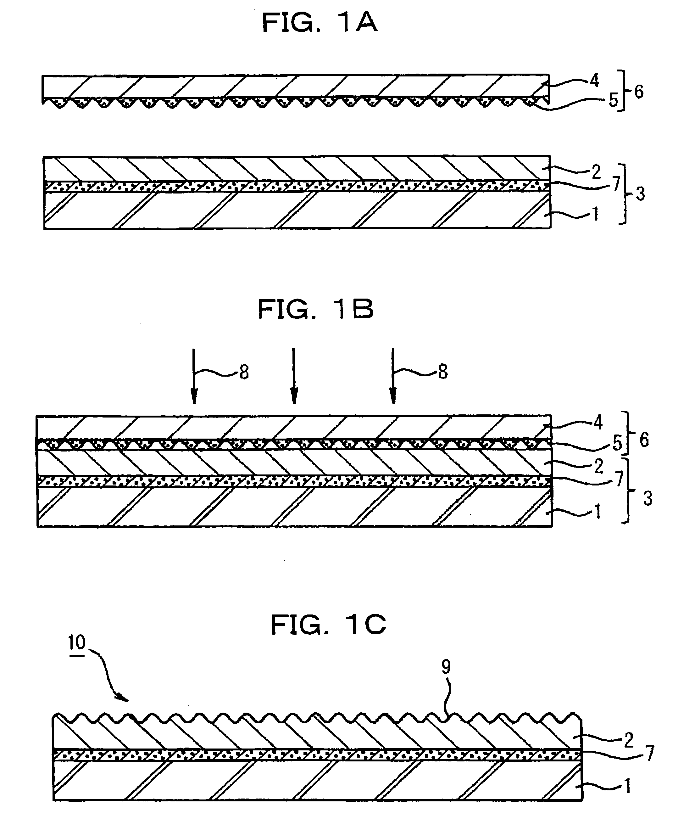
A photothermal conversion layer and UV curable resin layer (not-yet-cured but solid and thermoplastic) were successively formed on the surface of a substrate of a polyethylene terephthalate (PET) sheet. The surface of the not-yet-cured UV curable resin layer and a relief pattern sheet (OVD sheet) in which the diffraction lattice pattern (OVD) as a master hologram was grooved were closely attached by vacuum adsorption method to obtain a laminate.

Next, using semiconductor laser with wavelength of 808.5 nm as the laser, the above-mentioned laminate was set on XY stage while the substrate side being set in the laser irradiation side and the XY stage shown in FIG. 3 was moved to the starting point for drawing. When drawing image was instructed from PC, based on the image drawing program, the XY stage was moved according to the output image pattern so as to move the laser irradiation position and at the same time the irradiation of the IR laser was repeatedly turned on and off to draw ...
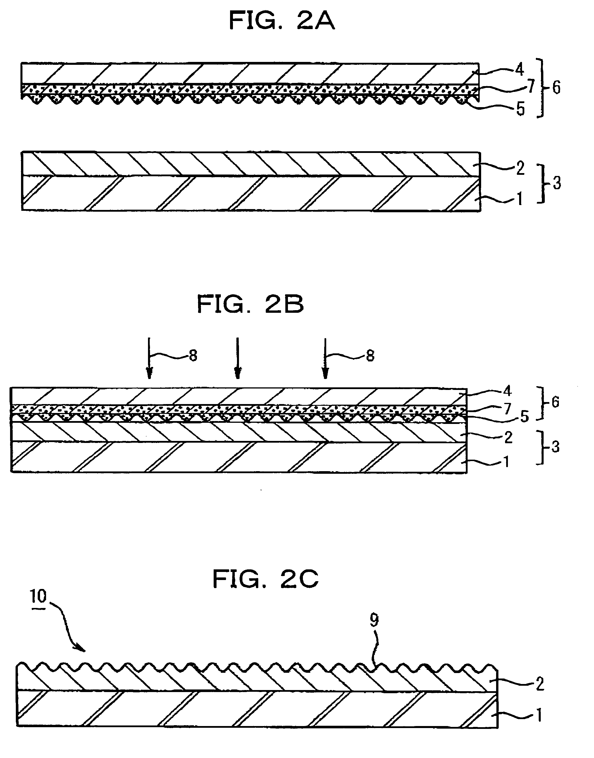
example 2

A UV curable resin layer (not-yet-cured but solid and thermoplastic) was formed on the surface of a substrate of a polyethylene terephthalate (PET) sheet, and the surface of the not-yet-cured UV curable resin layer and a relief pattern sheet (OVD sheet) in which the diffraction lattice pattern (OVD) as a master hologram was grooved and the photothermal conversion layer was formed were closely attached by vacuum adsorption method to obtain a laminate and the laminate was irradiated with laser beam in the same manner as described in Example 1 to form the concavo-convex pattern form corresponding to the concavo-convex form of the OVD sheet of the relief pattern sheet on the UV-curable resin layer and a concavo-convex pattern formed body was obtained, in which the concavo-convex pattern of the diffraction lattice was formed on the surface of the substrate sheet. The materials, laser drawing method and apparatus same as those employed in Example 1 were used except that the photothermal ...


PUM

PropertyMeasurementUnit
lengthaaaaaaaaaa
diameteraaaaaaaaaa
wavelengthaaaaaaaaaa

Abstract

A method for forming fine concavo-convex patterns by using a relief formation material 3 having a relief formation layer 2 composed of a resin having thermoplasticity and a relief pattern sheet 6 having on a surface thereof fine concavo-convex patterns 5, wherein a photothermal conversion layer 7 is formed in the relief formation material 3 or the relief pattern sheet 6; the photothermal conversion layer 7 is irradiated with light 8 to make the photothermal conversion layer 7 generate heat in the state that the relief formation layer 2 is brought into contact with the fine concavo-convex patterns 5; and the fine concavo-convex patterns 5 are formed on the relief formation layer 2.

Description

BACKGROUND OF THE INVENTION 1. Field of the Invention The present invention relates to a method for forming fine concavo-convex patterns in which relief holograms and diffraction lattices are recorded, a method for producing an optical diffraction structure composed of fine concavo-convex patterns, and a method for copying an optical diffraction structure. 2. Description of Related Art Relief holograms and diffraction lattices are for recording interference fringes formed by interfering laser beams in form of fine concavo-convex patterns. The fine concavo-convex patterns are composed of several hundred to thousand fine projections in every 1 mm length. In the case of copying the fine concavo-convex patterns, a copying forme is produced from a master hologram in which the interference fringes of laser beams are directly recorded and the concavo-convex patterns of the copying forme are transferred to a resin material to copy the fine concavo-convex patterns by mass production. I...

Claims


Application Information

Patent Timeline
Patent Type & Authority Applications(United States)
IPC IPC(8): B29C35/08B29C37/00B29C59/02G02B5/18G03H1/02G03H1/26
CPCB29C35/0888G03H2230/10B29C59/022B29C2035/0827B29C2035/0838B29C2059/023G02B5/1852G02B5/1857G03H1/0236G03H1/0276G03H1/26G03H2001/0284G03H2001/0428G03H2001/205G03H2001/2273G03H2210/32G03H2210/54G03H2210/55G03H2224/06B29C37/0053B29C2035/0822
Inventor FUNADA, HIROSHIMIZUKAMI, FUMIHIKOMATSUYAMA, TETSUYA
Owner DAI NIPPON PRINTING CO LTD
Why Eureka
Try Eureka