
Method and apparatus for optical noise cancellation

a technology of optical noise cancellation and optical sensor, applied in the direction of electrical apparatus, distortion/dispersion elimination, fibre transmission, etc., can solve the problems of discontinuities producing background noise levels, present problems to system designers, and reducing measurand resolution, so as to increase the signal-to-noise ratio

Inactive Publication Date: 2005-03-17
WEATHERFORDLAMB
View PDF13 Cites 15 Cited by
  • Summary
  • Abstract
  • Description
  • Claims
  • Application Information

AI Technical Summary

Benefits of technology

[0010] An apparatus that is in accord with the principles of the present invention includes a light source for producing an optical signal. The optical signal from the light source, which can be a tunable laser or a broadband light source coupled to a tuned optical filter, is applied to a remote optical element that is subject to optical background noise. The optical signal is modified by the optical element and is reflected back to (or passes to) a receiver. The reflected optical signal is analyzed to determine the amount of noise. If the noise is broadband, the average noise level is subtracted from the composite signal, thus increasing the signal to noise ratio. If the noise is periodic, the analysis includes a Fourier analysis (or an equivalent frequency analysis technique). The periodic noise frequencies are then filtered from the range of possible signal frequencies.

Problems solved by technology

While very long sensor arrays can be useful, they can present problems to system designers.
Such reflections produce spurious optical noise signals that can lead to a reduction in measurand resolution.
With incoherent light, the discontinuities produce an intensity background noise level.
More ominously, with coherent light, such as that produced by laser light sources, such discontinuities can produce periodic signals that can interfere with the Bragg element reflections.

Method used


Image

  • Method and apparatus for optical noise cancellation
  • Method and apparatus for optical noise cancellation
  • Method and apparatus for optical noise cancellation

Examples


Embodiment Construction

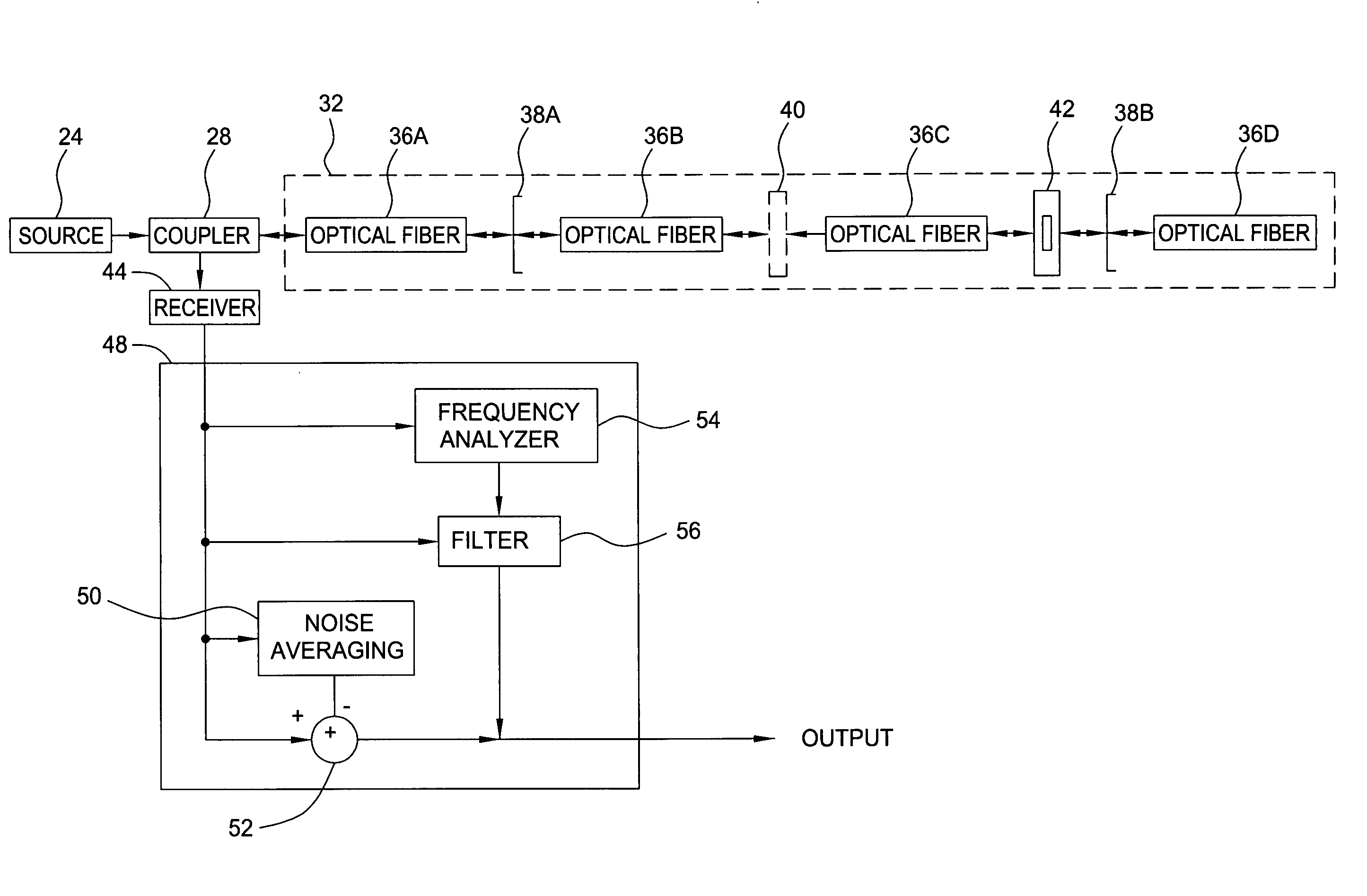
[0018]FIG. 1 illustrates a generalized apparatus 20 that is in accord with the principles of the present invention. That apparatus includes a light source for producing an optical signal, such as a scanning optical source 24 that produces a narrow bandwidth beam that sweeps across an optical spectrum. An optical signal produced by the optical source 24 is applied to a coupler 28 that couples the sweeping narrow bandwidth beam to an optical fiber network 32, e.g. an optical sensor array. The optical fiber network 32 includes multiple optical fiber sections, 36A-36D, which are coupled together by splices 38A and 38B and a connector 40. The splices 38A and 38B and the connector 40 represent discontinuities in the optical fiber network 32. The optical fiber network 32 also includes an FBG element 42. For simplicity, only one FBG element 42 is shown. Generally, the network 32 will comprise a plurality of FBG elements.

[0019] It should be understood that the subject invention is not limit...


PUM


Abstract

A method and apparatus for removing optical noise from an optical system. A light source produces optical signals applied to a remote optical element that produces reflected optical signals and is subject to optical background noise such as reflections from splices and optical connections. Part of the reflected optical signals and at least some of the background noise is applied to a receiver. The receiver output is analyzed to determine either the amount of noise (if broadband) or the frequency components of the noise. If broadband, the noise is subtracted from the composite signal, thus increasing the signal to noise ratio. If periodic, the frequency components of the noise are gated out of the receiver output.

Description

BACKGROUND OF THE INVENTION [0001] 1. Field of the Invention [0002] This invention relates to optical sensor systems. More particularly, this invention relates to a technique for reducing noise in fiber optic systems. [0003] 2. Description of the Related Art [0004] Fiber Bragg grating (FBG) elements have been successfully used as sensors in inhospitable locations such as down hole in oil wells. An FBG element is usually formed by photo-induced periodic modulation of the refractive index of an optical fiber's core. An FBG element is highly reflective to light having wavelengths within a narrow bandwidth centered at a wavelength that is referred to as the Bragg wavelength. While wavelengths that are very close to a Bragg wavelength are highly reflected, other wavelengths are passed without reflection. Since the Bragg wavelength is dependent on physical parameters such as temperature and strain that alter the refractive index of the FBG element, an FBG element can be used to measure su...

Claims


Application Information

Patent Timeline
Patent Type & Authority Applications(United States)
IPC IPC(8): H04B10/18
CPCH04B10/2513
Inventor MACDOUGALL, TREVORTAVERNER, DOMINO
Owner WEATHERFORDLAMB
Learn More