Floating modular breakwater

a technology of modular breakwaters and breakwaters, which is applied in the field of floating modular breakwaters, can solve the problems of reducing the height of slow waves, requiring special equipment, and expensive equipment, and achieves the effect of establishing buoyancy and positioning the array in the water

Inactive Publication Date: 2005-03-17
STEINBERG DOV
View PDF23 Cites 36 Cited by
  • Summary
  • Abstract
  • Description
  • Claims
  • Application Information

AI Technical Summary

Benefits of technology

[0018] According to still an application of the present invention, a deck is mounted on the breakwater, for easy access along the breakwater and optionally for transfer facilities such as electricity, fresh water supply, sewage suction, communication cables, etc. The deck may be

Problems solved by technology

One type of such breakwater requires employment of massive seabed foundations which are time consuming in setting up, as well as expensive and requiring special equipment for deployment thereof.
However, floating breakwater structures have some disadvantages setting as examples ineffectiveness

Method used


Image

  • Floating modular breakwater
  • Floating modular breakwater
  • Floating modular breakwater

Examples


Embodiment Construction

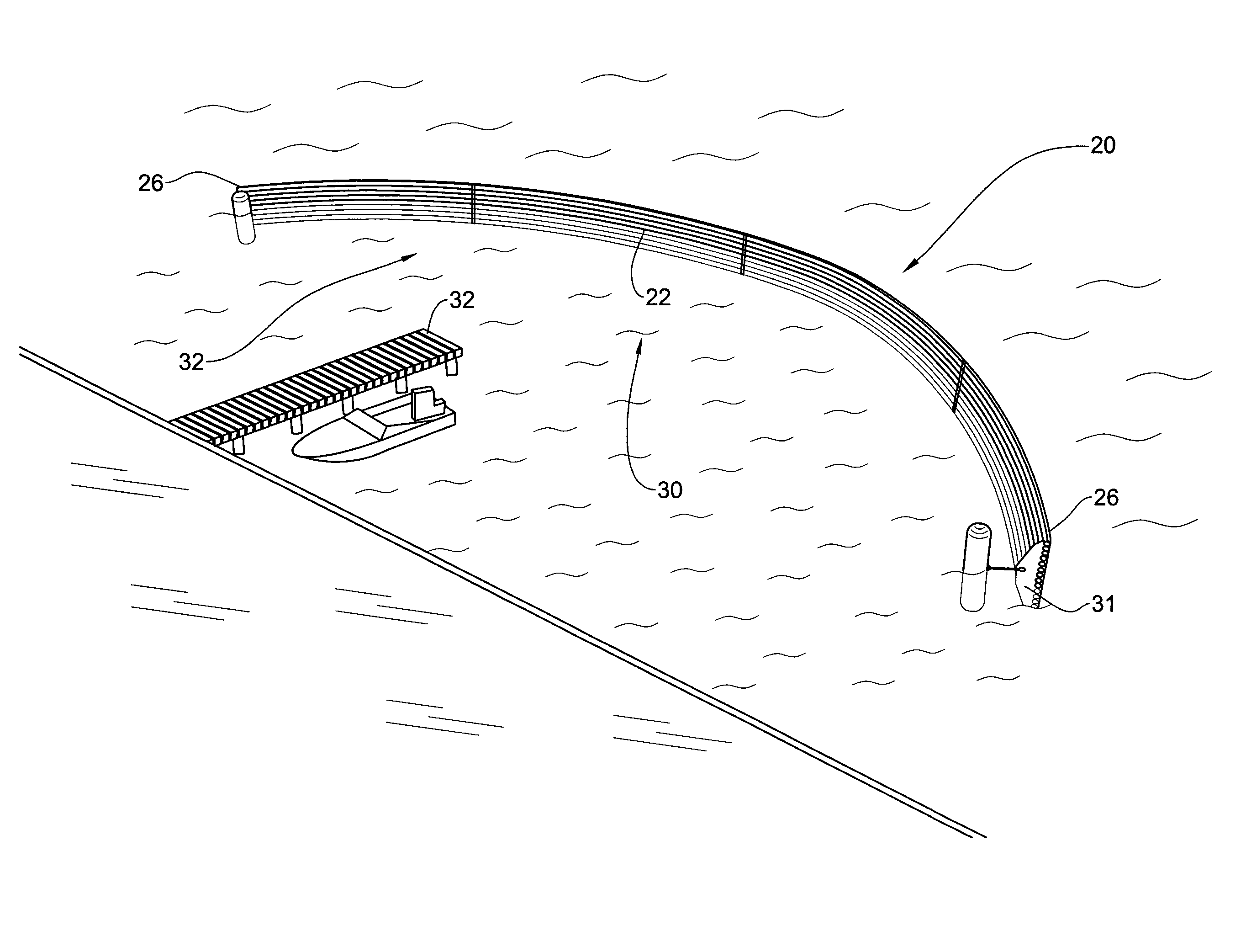
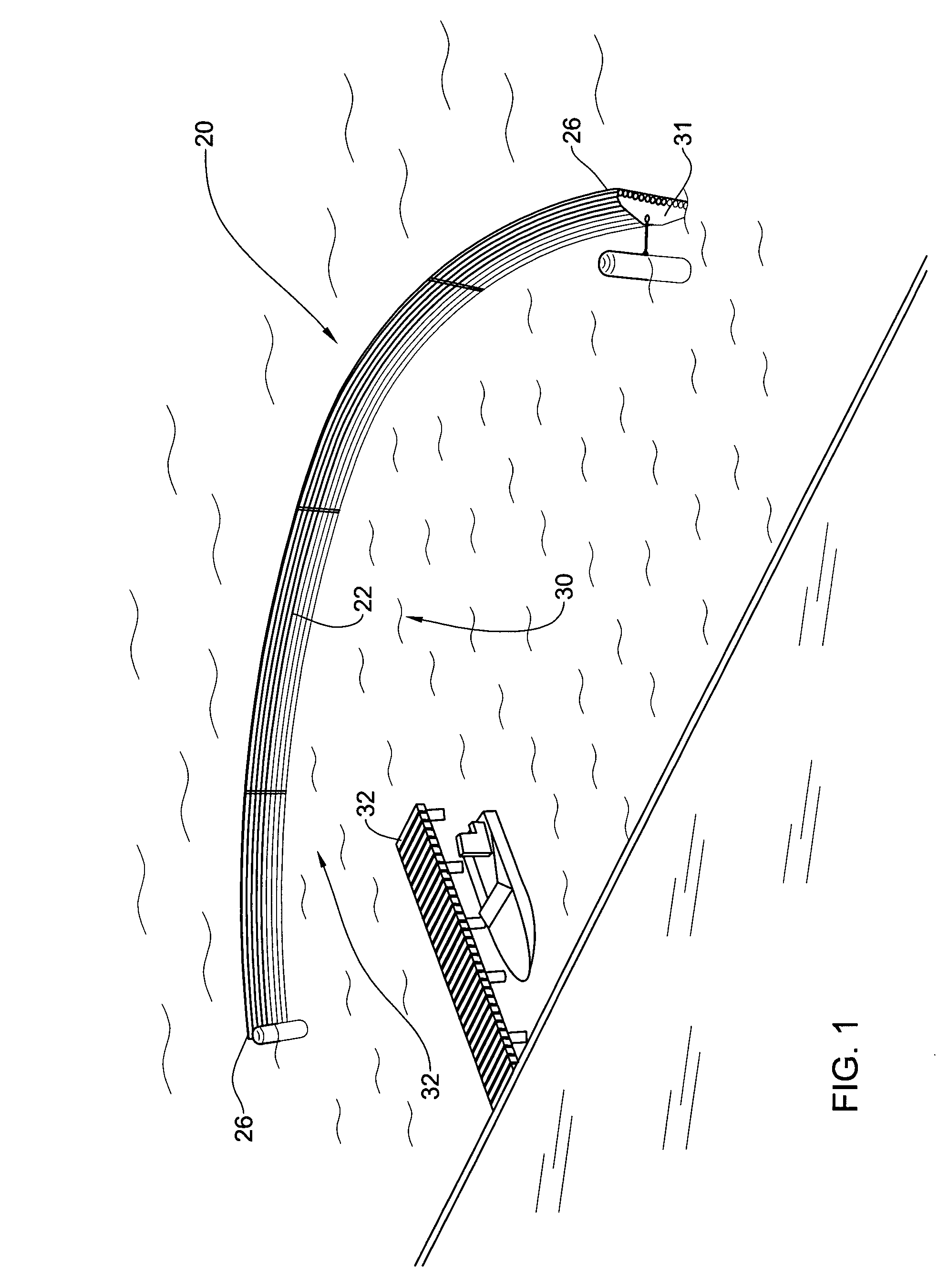
[0037]FIG. 1 is a bird's view of a breakwater in accordance with an embodiment of the present invention generally designated 20 comprising an array of rods 221o fixedly secured as will become apparent hereinafter and retained in the open waters at an arced / bowed configuration by means of bending force applied to respective ends 26 of the array thereby attenuating waves at the area designated 30, offering reduced sea state wave conditions around the deck 32.

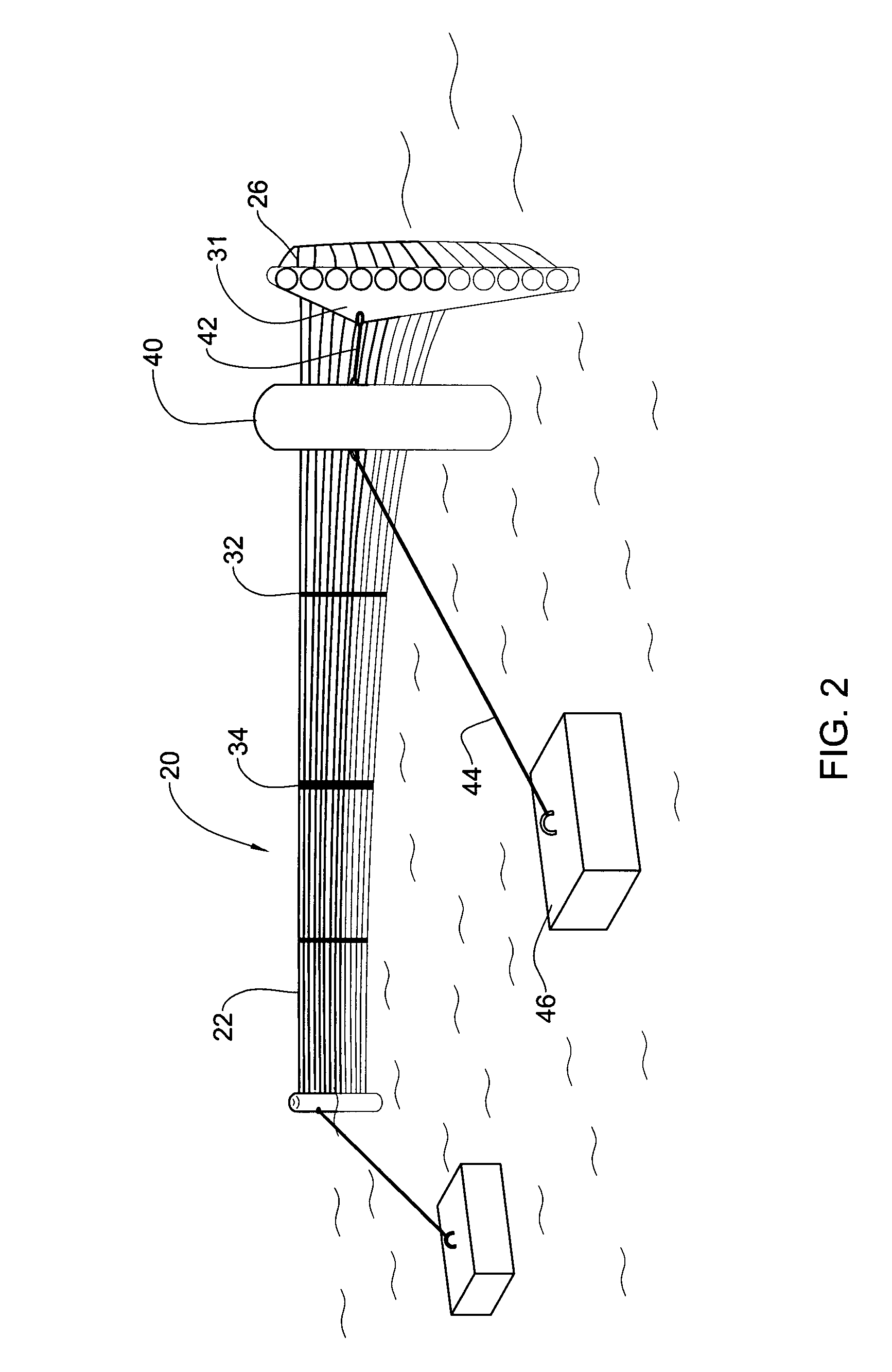
[0038] With further attention directed also to FIG. 2, the breakwater 20 is seen in more detail and it is noticed that the array 22 comprises a plurality of longitudinal rods 26 parallelly retained at a substantially vertical / upright position, partially submersed in the water.

[0039] The rods are typically manufactured by an extrusion process and are made, for example of any combination of materials such as plastic, epoxy, polyester and may be reinforced by various fibers such as Kevlar®, glass or charcoal fibers, etc., as known ...


PUM


Abstract

A floating breakwater assembly comprising an array of elongate rods articulated to one another for extending at a substantial vertical position at least partially submersed in water, wherein the rods are made of a flexible material and where the array is elastically deformable into an arcuate shape by bending the array.

Description

FIELD OF THE INVENTION [0001] The present invention generally relates to breakwaters, piers, docks, wave breakers, wharfs, etc., hereinafter in the specification and claims referred to collectively as breakwaters, used for protecting coasts namely shore lines and harbors, and offshore elements e.g. marine watercrafts and structures. More specifically the invention is concerned with floating such elements, useful in a variety of embodiments and different purposes. BACKGROUND OF THE INVENTION [0002] Maritime structures of the concerned type have many purposes. For example, they may be used to minimize wave damage and for erosion control of shores and structures (either at shoreline or at open waters). Furthermore, such structures may be used to form wharfs for ships to moor and for connecting with land. Other examples of use of such structures may be bounding of non-shore areas to define restricted areas, e.g. a swimming zone, maritime sports zone etc. Alternatively, such bounding may...

Claims


Application Information

Patent Timeline
IPC IPC(8): E02B3/06E02B3/20E02B15/04
CPCE02B3/062E02B3/064E02B15/0835E02B15/08E02B15/0814E02B3/20Y02A10/11
Inventor STEINBERG, DOV
Owner STEINBERG DOV
Why Eureka
Try Eureka