Devices for intraocular drug delivery

a technology eye, which is applied in the field of devices and methods for intraocular drug delivery, can solve the problems of limited ocular absorption, high risk of systemic toxicity for patients, and many challenges for patients to receive drugs to the eye, so as to reduce reduce the length of drug delivery implants, and increase the risk of eye damage. the effect of retina tissue and lens capsule damag

Inactive Publication Date: 2005-03-17
THE JOHN HOPKINS UNIV SCHOOL OF MEDICINE
View PDF38 Cites 64 Cited by
  • Summary
  • Abstract
  • Description
  • Claims
  • Application Information

AI Technical Summary

Benefits of technology

[0013] We have found the non-linear shape of the body member provides a number of advantages. The non-linear shape provides a built-in anchoring mechanism that prevents unwanted movement of the device and unwanted ejection of the device out of the eye since the non-linear shape of the body member requires manipulation of the device to get it out of an incision. For example, in a preferred embodiment, wherein the implant is in the shape of a coil, the device can be removed only by twisting the device out of the eye and, thus, is not susceptible to ejection by the eye or unwanted movement within the eye. Further, the non-linear shape geometry of the body member provides greater surface area per length of the device. This is advantageous because it is desirable to limit the length of drug delivery implants to prevent the implant from entering the central visual field (See FIG. 6 which follows). If the implant enters the central visual field, this will result in blind spots in the patient's vision and will increase the risk of damage to the retina tissue and lens capsule. By forming the body member in a non-linear shape, the device of the present invention holds a greater volume of materials per length of the device and it also provides a larger surface area per length of the device through which the material may be delivered.

Problems solved by technology

The delivery of drugs to the eye presents many challenges.
High systemic doses can penetrate this blood ocular barrier in relatively small amounts, but expose the patient to the risk of systemic toxicity.
Topical delivery of drugs often results in limited ocular absorption due to the complex hydrophobic / hydrophilic properties of the cornea and sclera.
However, these repeated intraocular injections carry the risk of infection, hemorrhage and retinal detachment.
Patients also find this procedure somewhat difficult to endure.
Because the overall shape of the capsule is linear, the amount of drug that may held by the device and that may be delivered over the surface area of the device is limited.
If the width of the capsule is increased, excessive sized incisions will be required for insertion of the device.
If the length of the capsule is increased to greater than 1 cm, the implant will pass into the central visual field of the eye, thereby causing blind spots in the patient's eye as well as increase risk of damage to the retinal tissue and lens capsule.
Thus, many agents cannot be effectively delivered from such a system because their permeation rate through the rate controlling material of the system is too small to produce a useful effect.
Other agents cannot be satisfactorily delivered by diffusional devices because of a particular chemical characteristic of the agent.
This includes salts, because of their ionic character, and unstable polar compounds that cannot be formulated into a composition suitable for storage and delivery from such systems.
Because the overall shape of the capsule is linear, the amount of drug that may held by the device and the surface area through which the drug may be delivered is limited.
If the width of the capsule is increased, excessive sized incisions will be required for insertion of the device.
If the length of the capsule is increased to greater than 1 cm, the implant will pass into the central visual field of the eye, thereby causing blind spots in the patient's eyes well as increase risk of damage to the retinal tissue and lens capsule.

Method used


Image

  • Devices for intraocular drug delivery
  • Devices for intraocular drug delivery
  • Devices for intraocular drug delivery

Examples


Embodiment Construction

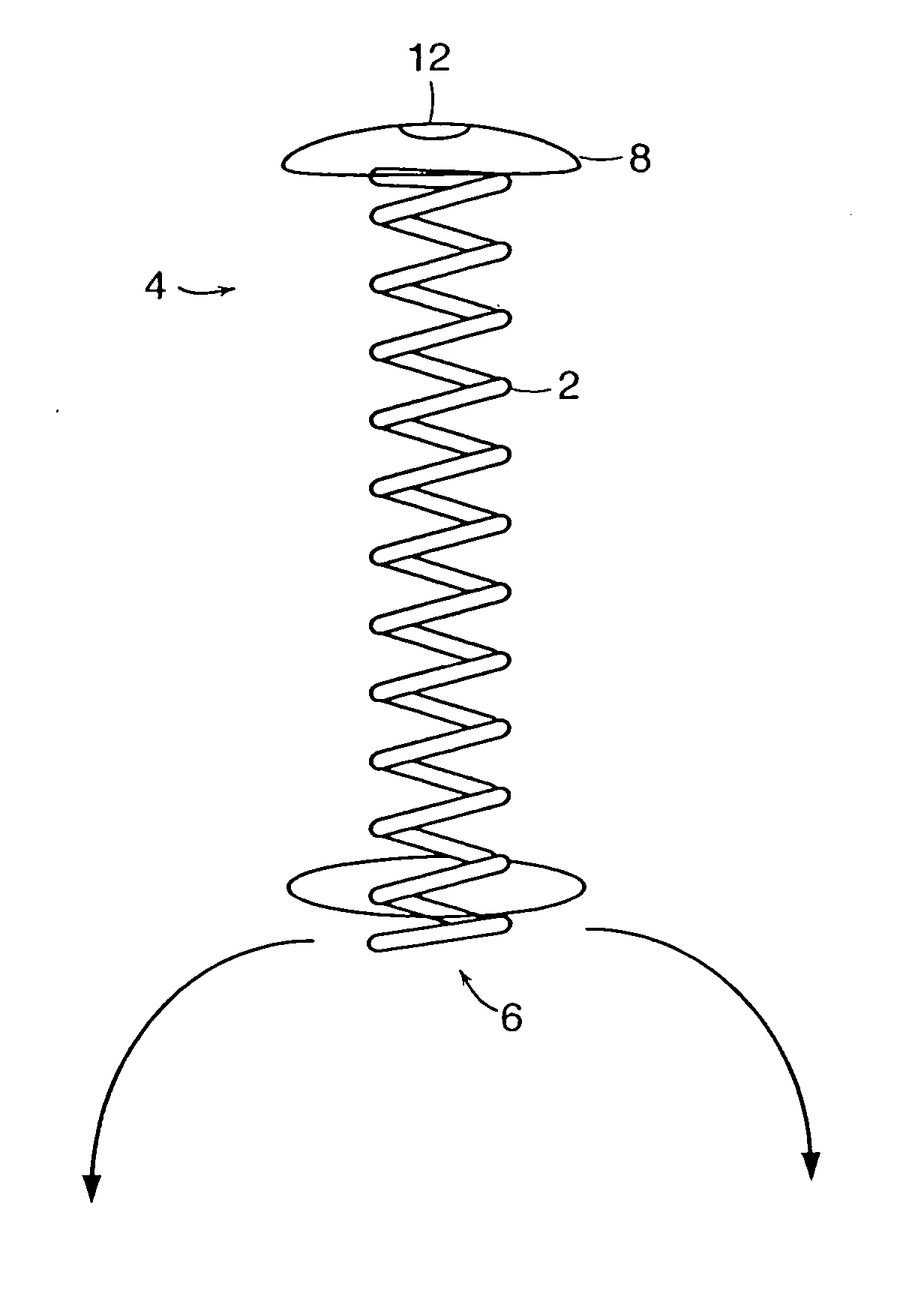
[0033] As discussed above, preferred delivery devices of the invention have a non-linear (arcuate) shape during residence within a patient's eye. Preferred designs have multiple turns or angles. For example, preferred designs the device has at least two, three, four, five, six, seven, right, nine or ten separate deviations from a linear path. A coil design is particularly preferred, although other multiple-angle configurations are also suitable such as a substantially Z-shape and the like.

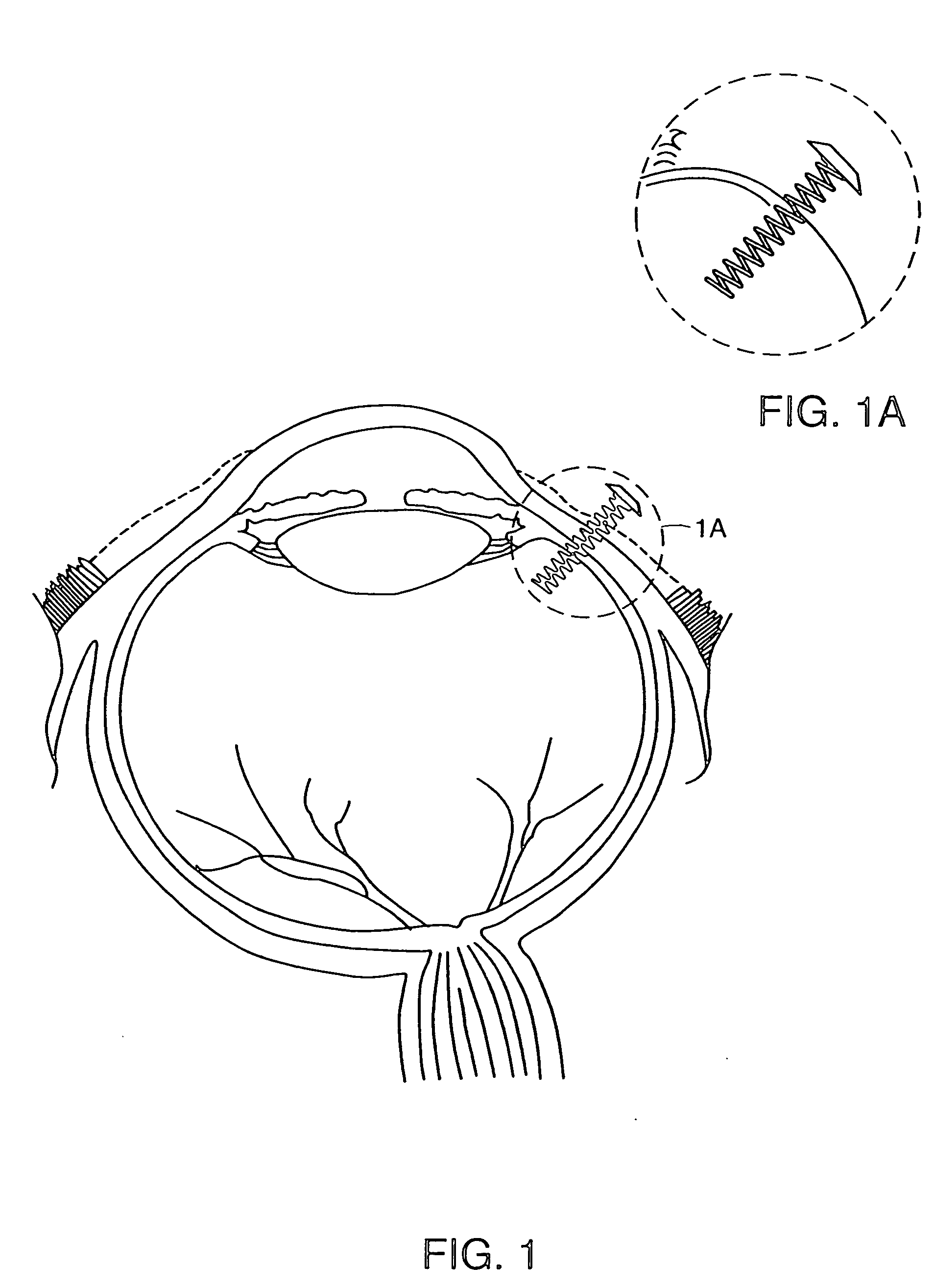
[0034] Referring now to the various figures of the drawing, wherein like reference characters refer to like parts, there is shown various views of a delivery device 1, in accordance with the invention.

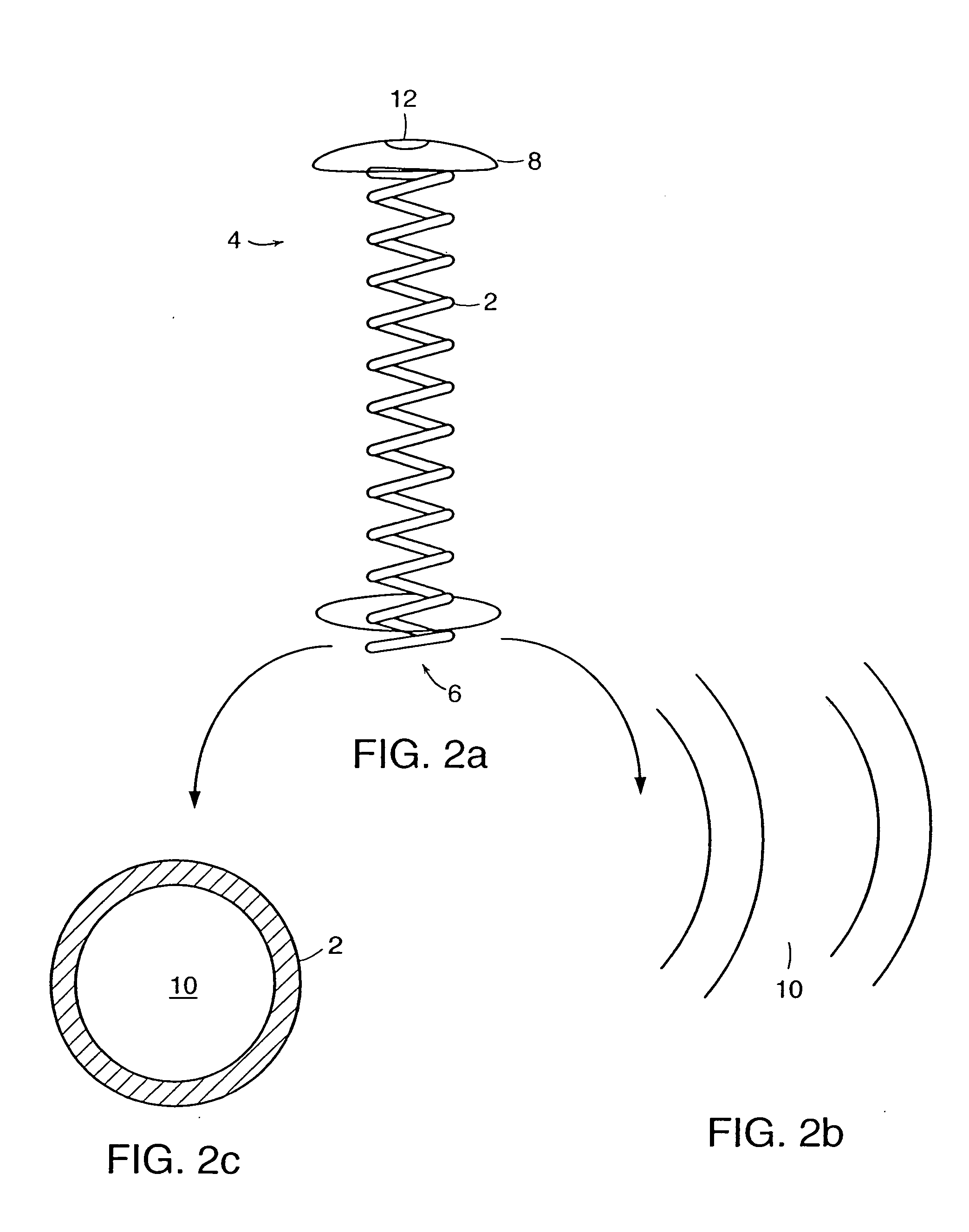
[0035] As shown in FIGS. 1-5c, the delivery device 1 includes a non-linear shaped body member 2 having a proximal end 4, a distal end 6. In one preferred embodiment, the body member 2 has a coil shape, as shown in FIGS. 1-5c. However, the shape of the body member 2 is not limited to a coil shape and...


PUM

PropertyMeasurementUnit
lengthaaaaaaaaaa
lengthaaaaaaaaaa
distanceaaaaaaaaaa

Abstract

An therapeutic agent delivery device that can allows is particularly suitable for delivery of a therapeutic agent to limited access regions, such as the posterior chamber of the eye and inner ear. Preferred devices of the invention are minimally invasive, refillable and may be easily fixed to the treatment area. Preferred delivery devices of the invention also include those that comprise a non-linear shaped body member body housing one or more substances and a delivery mechanism for the sustained delivery of the one or more substances from the non-linear shaped body member to the patient.

Description

[0001] The present application claims the benefit of U.S. provisional application 60 / 228,934, filed Aug. 30, 2000, which is incorporated herein by reference in its entirety.FIELD OF THE INVENTION [0002] The present invention relates to a device and method for intraocular delivery of therapeutic agents. Preferred devices of the invention include a non-linear portion that resides within a patient's eye during use that can facilitate the delivery of a therapeutic agent. BACKGROUND [0003] The delivery of drugs to the eye presents many challenges. The ocular absorption of systemically administered pharmacologic agents is limited by the blood ocular barrier, namely the tight junctions of the retinal pigment epithelium and vascular endothelial cells. High systemic doses can penetrate this blood ocular barrier in relatively small amounts, but expose the patient to the risk of systemic toxicity. Topical delivery of drugs often results in limited ocular absorption due to the complex hydrophob...

Claims


Application Information

Patent Timeline
Patent Type & Authority Applications(United States)
IPC IPC(8): A61B17/00A61F9/007A61F9/00A61K9/00A61K9/22A61K45/00A61L31/00A61P27/02
CPCA61B2017/00867A61K9/0051A61F9/0017A61P27/02
Inventor VARNER, SIGNE ERICKSONDEJUAN, EUGENE JR.SHELLEY, TERRYBARNES, AARON CHRISTOPHERHUMAYUN, MARK
Owner THE JOHN HOPKINS UNIV SCHOOL OF MEDICINE
Why Eureka
Try Eureka