
Redistribution metal for output driver slew rate control

a technology of output driver and redistribution metal, which is applied in the field of integrated circuit devices, can solve the problems of forming hundreds of interconnects between a chip and a circuit board, limiting the performance achievable in an integrated circuit system, and requiring more complex devices to connect hundreds of interconnects, etc., and achieves the elimination of circuit complexity, cost, and associated chip real estate.

Inactive Publication Date: 2005-03-17
BROADCOM INT PTE LTD
View PDF11 Cites 1 Cited by
  • Summary
  • Abstract
  • Description
  • Claims
  • Application Information

AI Technical Summary

Benefits of technology

[0017] The invention uses no additional circuitry for controlling the slew rate of integrated circuit signals, and therefore eliminates the circuit complexity, cost, and associated chip real estate corresponding to prior art methods for achieving the same result.

Problems solved by technology

As integrated circuit devices become increasingly faster and more complex, the performance achievable in an integrated circuit system can be limited by the interconnections between such devices with one another and with other components on a circuit board.
Whereas integrated circuit devices once had only a few interconnects, often hundreds of interconnects are now required in more complex devices.
Forming hundreds of interconnects between a chip and circuit board, however, can be difficult since chips are typically fabricated with significantly finer resolution than that of circuit boards.
System performance is often limited by noise on signals transmitted between between a chip package and a circuit board.
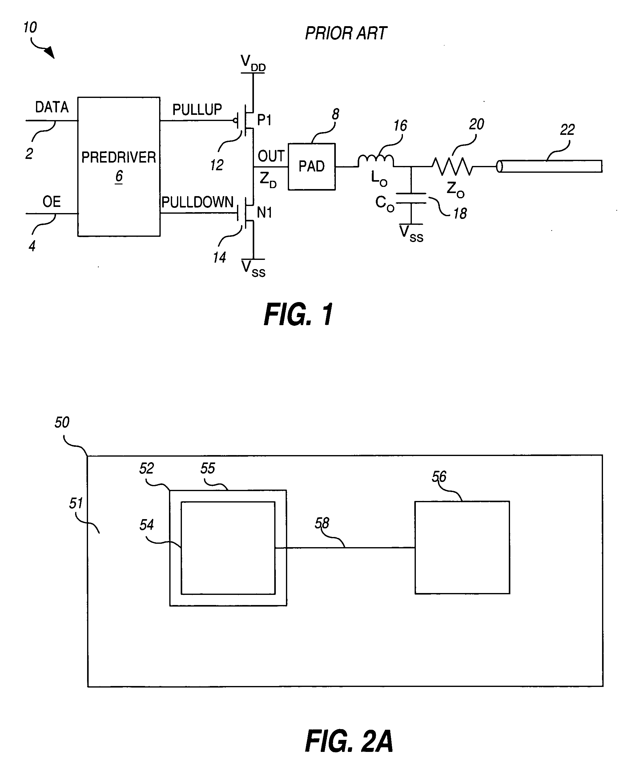
One predominant form of noise results from parasitic capacitance, inductance, and resistance due to the signal routing between the signal pad on the integrated circuit die and the circuit board trace.
For example, one predominant problem resulting from transmission line parasitics is known as “simultaneously switching output” (SSO) noise.
SSO noise occurs when multiple signals in close proximity to one another switch at the same time.
The switching activity causes a large current spike flowing through the power and ground connections, resulting in power and ground supply bounce.
Accordingly, the faster the switching speed, the higher the SSO noise.
Reflection noise may also occur when the switching frequency approaches the RC time constant of the transmission line.
The fast rise and fall of the high-speed signals on the line causes transients on the power supplies and undesirable wave reflections causing overshoot and undershoot.
Crosstalk noise arises when signals on parallel transmission lines are located too close in proximity to one another.
Thus, the faster the rise time of the signal, the greater the crosstalk noise
Another predominant problem that occurs with integrated circuit output drivers is known as “power supply droop”.
When several I / O drivers are attached to any one power pad, the demands on the power supply from the output drivers can cause signal droop on the power bus.
Signal droop is problematic because it decreases the maximum current flow through the pullup driver PFET P2 and therefore decreases the speed at which the signal transitions to the high state.
Thus, reflection noise is generated when the signal switching speed approaches the decreased rise time due to the power droop.
Similar problems occur with the ground supply.
However, additional circuitry involves additional complexity, cost, and chip real estate.

Method used


Image

  • Redistribution metal for output driver slew rate control
  • Redistribution metal for output driver slew rate control
  • Redistribution metal for output driver slew rate control

Examples


Embodiment Construction

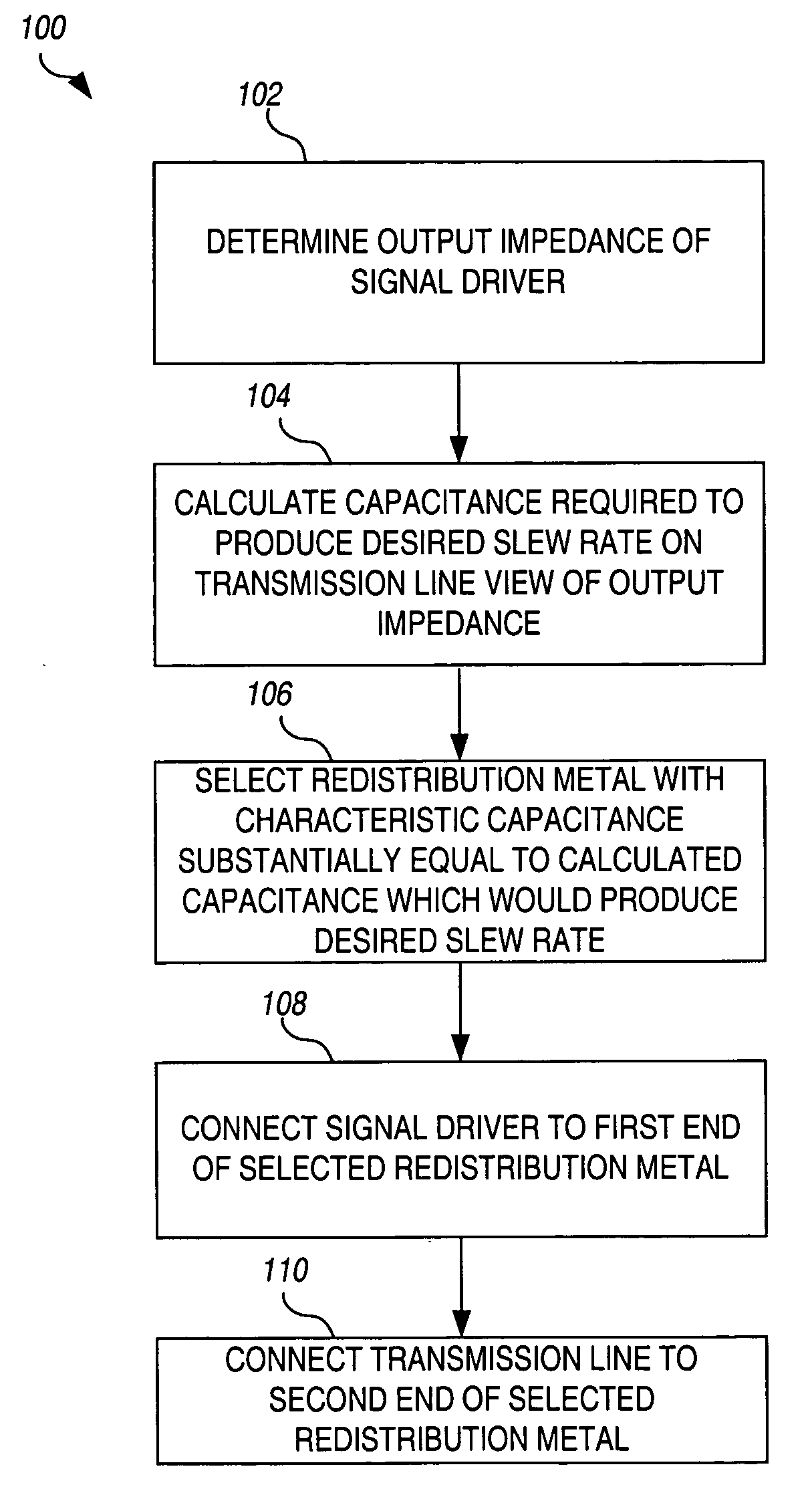
[0031] A novel technique for controlling the slew rate of output signals of integrated circuits using signal redistribution metal is described in detail hereinafter. Although the invention is described in terms of specific illustrative embodiments, it is to be understood that the embodiments described herein are by way of example only and the scope of the invention is not intended to be limited thereby.

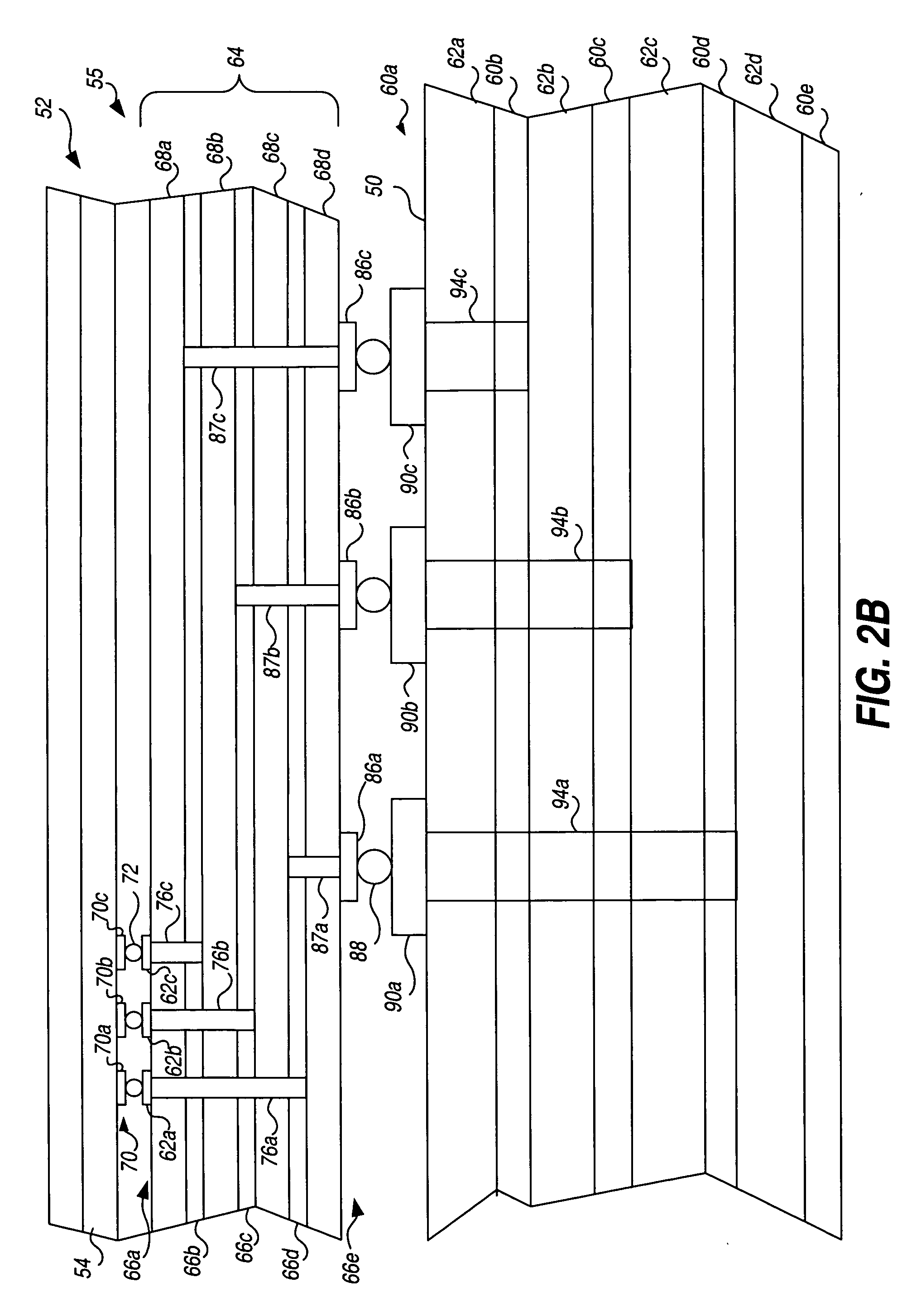
[0032]FIGS. 2A-2C illustrate the connection of an I / O integrated circuit pad with a circuit board transmission line via redistribution metal. FIG. 2A is a top view of a conventional circuit board 50 having a first surface 51 with at least one integrated circuit 52 mounted thereon. Integrated circuit 52 comprises a die 54 packaged in a package 55 and disposed on first surface 51 of the circuit board 50. In the illustrative embodiment, integrated circuit 52 communicates with at least one electronic component 56 (such as another integrated circuit) via a conductive trace, or transmissio...


PUM


Abstract

A novel method is presented for mapping a signal driver of an integrated circuit to one of a plurality of interconnect pads. The output impedance of the signal driver and desired slew rate for a signal generated by the signal driver is used to calculate a desired characteristic capacitance to provide a resulting characteristic time constant required to achieve the desired slew rate on a transmission line connected to receive the signal. The characteristic capacitance associated with each at least one possible interconnection path between the driver and pad is estimated, and one of the interconnection paths whose associated characteristic capacitance is substantially equal to the desired characteristic capacitance is selected, and the output driver is then mapped to the pad associated with the selected interconnection path.

Description

CROSS REFERENCE TO RELATED APPLICATIONS [0001] This is a divisional of copending application Ser. No. 10 / 044,122 filed on Jan. 10, 2002, the entire disclosure of which is incorporated herein by reference. BACKGROUND OF THE INVENTION [0002] The present invention pertains generally to integrated circuit devices, and more particularly to a method for using redistribution metal to control the slew rate of output drivers. [0003] As integrated circuit devices become increasingly faster and more complex, the performance achievable in an integrated circuit system can be limited by the interconnections between such devices with one another and with other components on a circuit board. Whereas integrated circuit devices once had only a few interconnects, often hundreds of interconnects are now required in more complex devices. Forming hundreds of interconnects between a chip and circuit board, however, can be difficult since chips are typically fabricated with significantly finer resolution t...

Claims


Application Information

Patent Timeline
IPC IPC(8): G06F17/50
CPCG06F17/5036G06F30/367
Inventor GONZALEZ, JASON
Owner BROADCOM INT PTE LTD
Learn More