Transceiver circuit for an ultrasonic flowmeter

a technology of ultrasonic flowmeter and transducer, which is applied in the direction of liquid/fluent solid measurement, volume/mass flow by dynamic fluid flow effect, instruments, etc., can solve the problems of group running time difference between upstream and downstream signal transmission, two systems are relatively complex, and the transducer decay time is not easy to detect, so as to reduce the coupling effect of signal

Inactive Publication Date: 2005-03-24
SIEMENS FLOW INSTR +1
View PDF14 Cites 13 Cited by
  • Summary
  • Abstract
  • Description
  • Claims
  • Application Information

AI Technical Summary

Benefits of technology

[0011] Based on the problem described, one object of the invention is to design a more simple transmitting and receiving circuit for an ultrasonic flowmeter, where the circuit exhibits full reciprocity and is not substantially affected by ringin

Problems solved by technology

DK 168 248 B1 discloses a system using separate transmitting and receiving circuits, thus running the risk of group running time differences of upstream and downstream signal transmission, as mentioned above.
The same applies for the system according to DK 166 974 B1, which consequently does not eliminate the problems of group running time differences.
Further, these two systems are relatively complex, with several switches and amplifiers.
With the embodiments described in DE 100 48 959 A1, it has turned out, however, that there is a problem with coupling of the signal from the generator to a receiving transducer and a problem with the decaying time of the transducers.
However, the ultrason

Method used


Image

  • Transceiver circuit for an ultrasonic flowmeter
  • Transceiver circuit for an ultrasonic flowmeter
  • Transceiver circuit for an ultrasonic flowmeter

Examples


Embodiment Construction

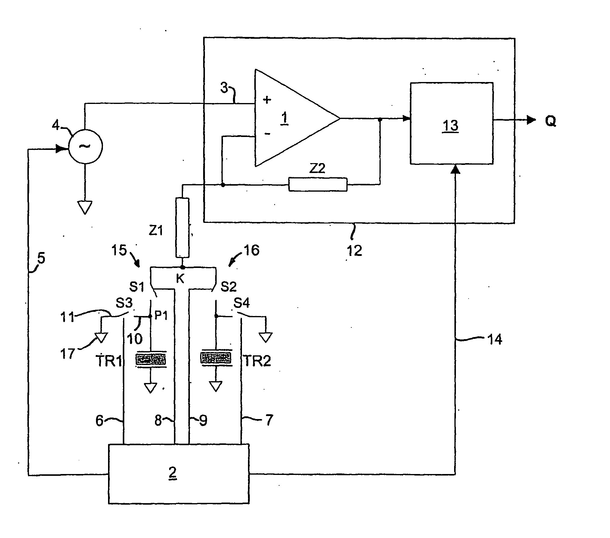
[0037] The transmitting and receiving circuit shown in FIG. 1 includes an amplifier 1 with a first, inverting input terminal for connection with an ultrasonic transducer TR1, TR2, the connection being established via an impedance Z1 and switching means S1, S2. S1 and TR1 here form a first series connection, whereas S2 and TR2 form a second series connection. The second, non-inverting input terminal is connected with a signal source, producing in a controlled manner electrical signals for transmission to the ultrasonic transducers TR1, TR2. A feedback connection is established between the output terminal and the inverting input terminal via an impedance Z2. The output terminal of the amplifier 1 is also connected with (not shown) detection means for the derivation of transit time measurements used for the calculation of the desired measured flow.

[0038] The circuit shown functions as follows:

[0039] During transmission from TR1 to TR2, S1 is closed, and the signal source supplies the...


PUM


Abstract

A transmitting and receiving circuit for an ultrasonic flowmeter. In such circuits, an ultrasonic transducer is typically used as both transmitter and receiver. This is obtained by using switching means, for example in the form of CMOS switches. However, problems arise with ringings of a transducer when having acted as a transmitter. This unwanted ringing makes the crystal of the transducer act as an additional signal generator, and the signal is coupled via parasitic capacitances in a switching means to the receiving ultrasonic transducer. This problem is solved by connecting one pole of a short circuit switch (S3, S4) to the ultrasonic transducer (TR1, TR2) or to the switching means (S1, S2) and the other pole of the short circuit switch to ground. Keeping the short circuit switch closed when the switching means is open, and open when the switching means is closed, creates a decoupling path for the unwanted signal, thereby improving the accuracy of the transmitting and receiving circuit.

Description

[0001] This is a Continuation of International Application PCT / DKO2 / 00705, with an international filing date of Oct. 24, 2002, which was published under PCT Article 21(2) in German, and the disclosure of which is incorporated into this application by reference.FIELD OF AND BACKGROUND OF THE INVENTION [0002] The present invention concerns a transmitting and receiving circuit for ultra-sonic flowmeters. The invention relates, particularly, to a transmitting and receiving circuit for an ultrasonic flowmeter, which includes a signal generator; and at least two circuit arrangements, each having a switching means and an ultrasonic transducer. [0003] In such circuits it is known that measuring the very small time differences between the transmission of ultrasound upstream and downstream requires a very high degree of symmetry in the electronic circuits used for transmitting and receiving ultrasonic signals via the transducers, so that the group running time for signals in the electronic ci...

Claims


Application Information

Patent Timeline
IPC IPC(8): G01F1/66
CPCG01F1/667
Inventor JESPERSEN, LARS
Owner SIEMENS FLOW INSTR
Why Eureka
Try Eureka