Bus network interface

a network interface and bus technology, applied in the field of network interface systems, can solve the problems of troublesome connection of multiple devices via a bus, unimportant connection of more than one meter, etc., and achieve the effect of low cost, simple and robust network

Inactive Publication Date: 2005-03-24
SPEDIANT SYST
View PDF3 Cites 4 Cited by
  • Summary
  • Abstract
  • Description
  • Claims
  • Application Information

AI Technical Summary

Benefits of technology

[0020] The MII interface includes sixteen signals, not including ground lines However, many of the MII signals can be combined, eliminated or ignored in a short-range bus-architecture network, yielding a simple, robust network at relatively low cost.

Problems solved by technology

Over short distances, parallel data transmission is advantageous because it allows the use of slower, cheaper electronic components, although it does require more data paths, and is subject to data timing problems, both of which problems are of only minor significance for short-distance data transmission.
It is often desirable to connect several devices in a private network in a limited space where cost and reliability are primary considerations, while the ability to support connections of more than approximately one meter is unimportant.
Connecting multiple devices via a bus presents a problem because more than one device may try to drive the bus at the same time.
This is especially troublesome if the driving devices include active pullup. FIG. 1 and FIG. 2 illustrate prior-art output drivers having active pullup.
Direct connection of the outputs of two or more active-pullup devices is considered poor practice in the art, because, in a situation where one device attempts to drive a high logic level and another device attempts to drive a low logic level, the resulting logic level is indeterminate, and large Currents flowing through the switching devices may damage the switching devices or other components of the system.
A wire-and connection without a pullup resistor 134 may operate, but is likely to be slow and unreliable, and thus neglecting to include a pullup resistor 134 is considered poor practice in the art.
If the central unit fails or is absent, the entire network is not usable.

Method used


Image

  • Bus network interface
  • Bus network interface
  • Bus network interface

Examples


Embodiment Construction

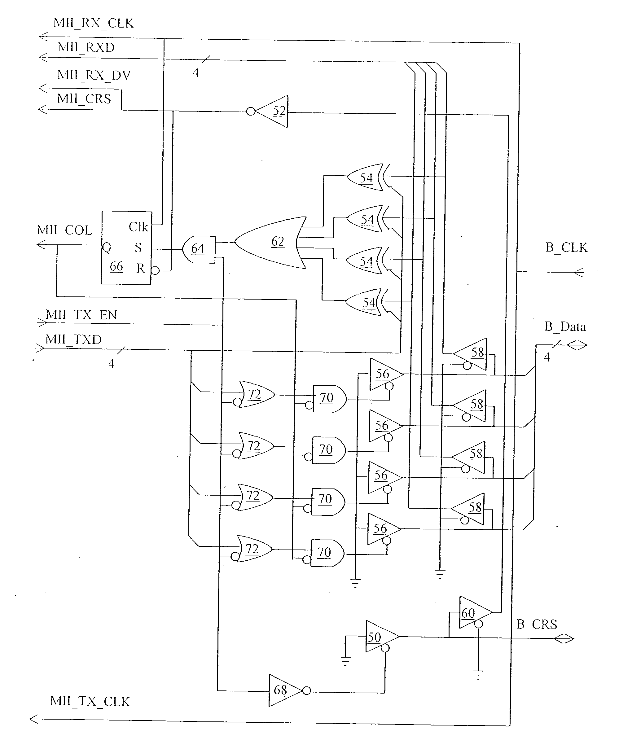
[0071] The present invention is of a network interface system having a bus architecture, and more particularly a system that facilitates the transfer of data among a collection of devices via a common bus without the need for connecting each device via a separate set of lines to a central unit.

[0072] The discussion below, by way of example only, shows how the present invention ma)y be applied to the connection of devices having MII interfaces via a bus architecture having a four-line parallel data path. However, the principles discussed apply to devices with interfaces other than MII, and to data paths having any number of lines, including a data path consisting of a single line. All such applications are included in the scope of the present invention.

[0073] The principles and operation of a network interface according to the present invention may be better understood with reference to the drawings and the accompanying description.

[0074] Referring now to the drawings, FIG. 7 illu...


PUM


Abstract

A system and method for transmitting data includes one or more transmitters connected to each of at least one bus data line via open-driver bus data line drivers, and one or more receivers. In a preferred embodiment, the devices are interconnected by a parallel interface using a bus architecture having the bus data and carrier-sense (CRS) lines each driven by open-collector or open-drain drivers in a wired-and configuration. Pullup resistors and a common clock signal are also provided. Each device is provided with an interfacing unit which connects the device to the bus, and detects collisions by comparing data transmitted by the device with data received from the bus. The invention is particularly applicable to implementation as a backplane connecting intercommunicating printed wiring boards having interfaces such as the IEEE 802.3 (Ethernet) Media Independent Interface (MII), the interfacing unit serving to emulate the Ethernet PHY.

Description

FIELD AND BACKGROUND OF THE INVENTION [0001] The present invention relates to a network interface system having a bus architecture: and more particularly to a system that facilitates the transfer of data among a collection of devices via a common bus without the need for connecting each device separately to a central unit. [0002] In a bus architecture, all of the devices on the network communicate via a common set of data lines. This is in contrast to some other network architectures wherein each device is connected to a hub or switch via an individual connection. [0003] The MII (Media-Independent Interface) is a standard interface specified in IEEE Standard 802.3, The Institute of Electrical and Electronics Engineers, New York, N.Y., 2000, which is incorporated by reference for all purposes as if fully set forth herein. The MII provides specifications for the connection of the Ethernet MAC (Media Access Control) layer to the Ethernet Physical (PHY) layer. The MII is incorporated in...

Claims


Application Information

Patent Timeline
Patent Type & Authority Applications(United States)
IPC IPC(8): G06F13/38H03K19/003H03K19/094
CPCG06F13/387
Inventor MAGAL, ELIEZEROSTER, ZEEV
Owner SPEDIANT SYST
Why Eureka
Try Eureka