

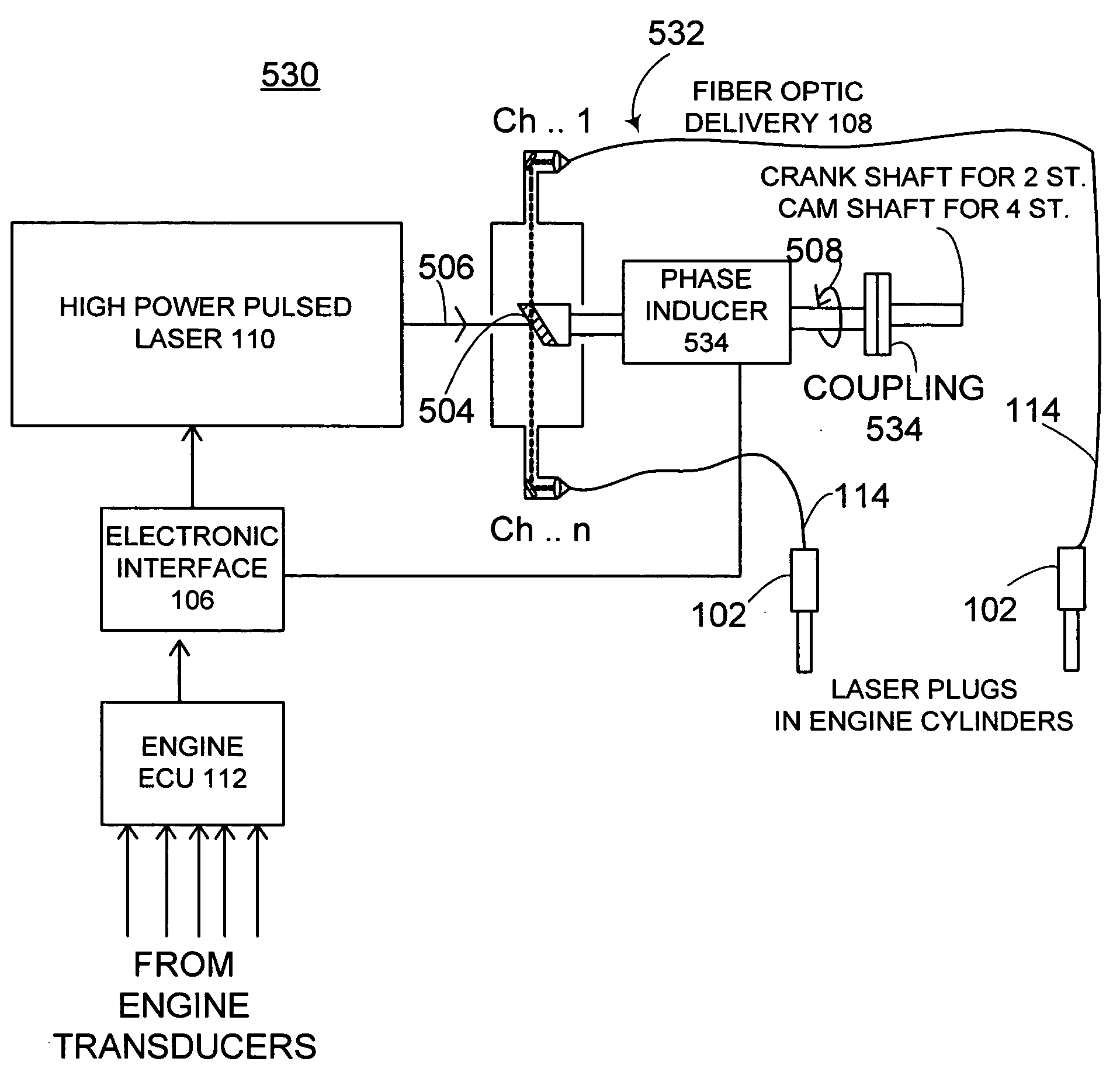
Laser based ignition system for natural gas reciprocating engines, laser based ignition system having capability to detect successful ignition event; and distributor system for use with high-powered pulsed lasers
a technology of laser based ignition and reciprocating engines, which is applied in the direction of electric control, machines/engines, instruments, etc., to achieve the effect of enhancing reflectivity
- Summary
- Abstract
- Description
- Claims
- Application Information
AI Technical Summary
Benefits of technology
Problems solved by technology
Method used
Image

Examples
Embodiment Construction
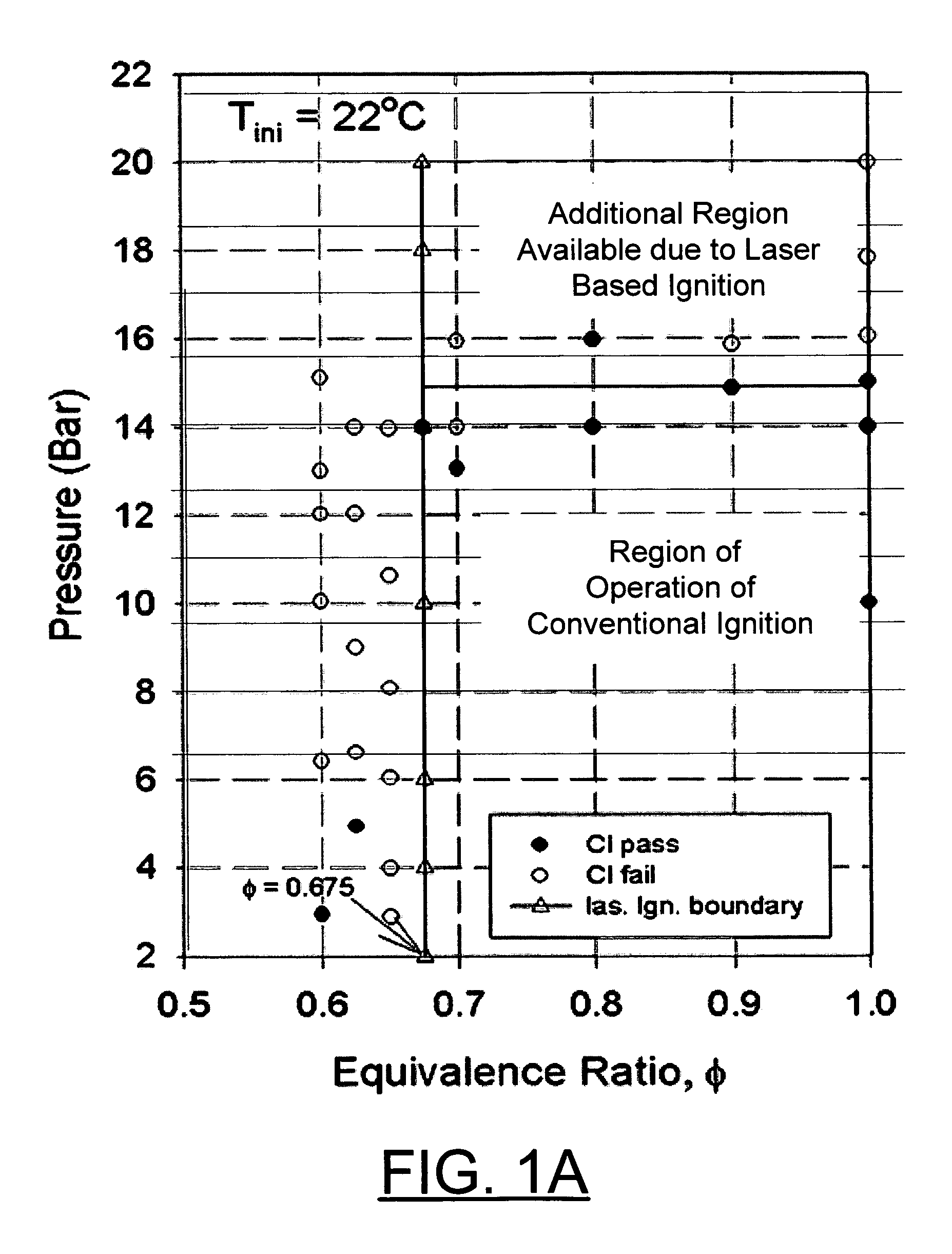
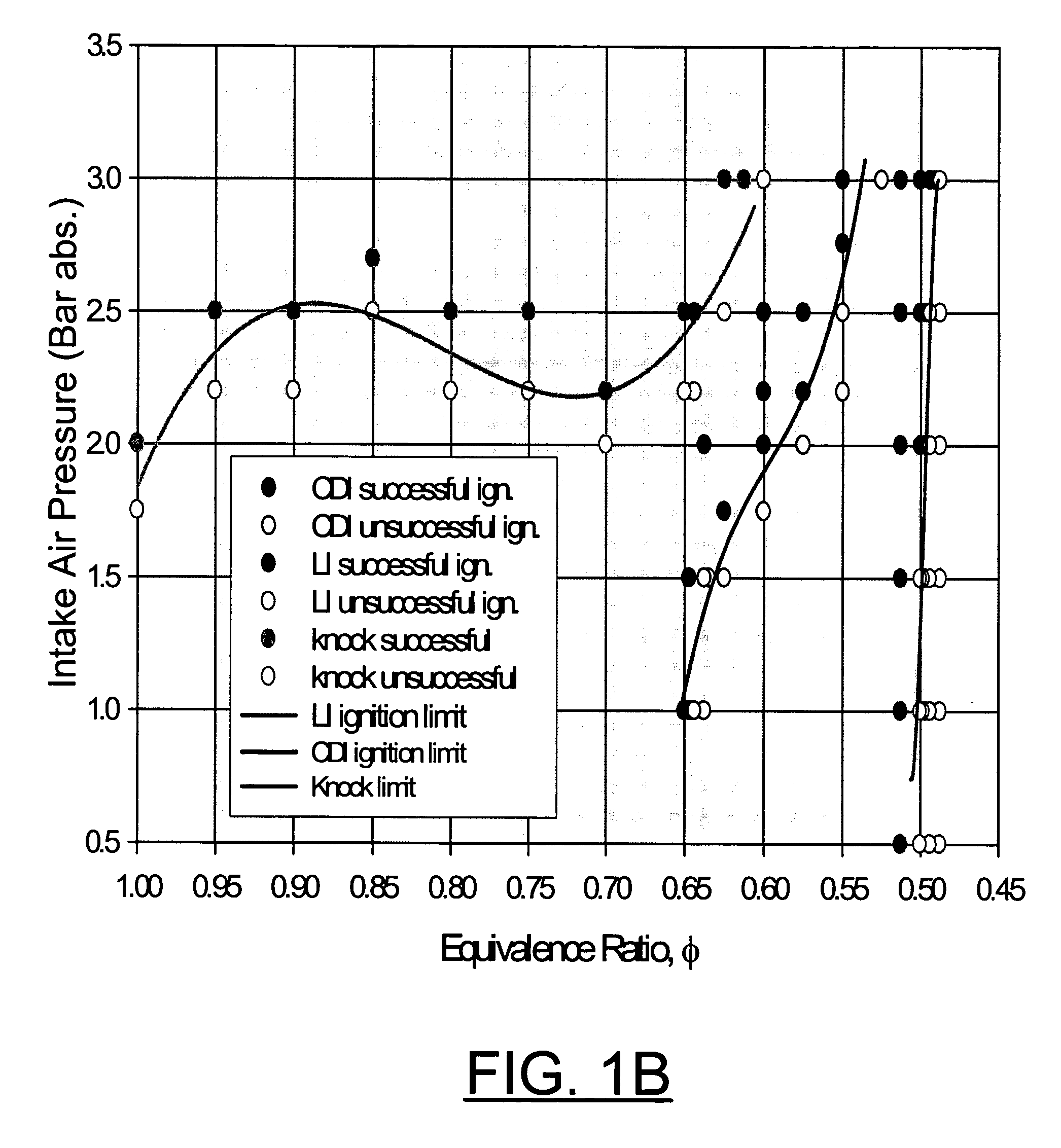
[0025] Having reference now to the drawings, in FIG. 1A there is shown a chart illustrating that laser based ignition enables ignition of natural gas and air mixtures at pressures higher than those limited by the performance limits of conventional coil based ignition systems. Also in FIG. 1B there is shown a chart illustrating that laser based ignition enables ignition of natural gas and air mixtures at equivalence ratios leaner than those limited by the performance limits of conventional coil based ignition systems. Such tests along with the fact that laser ignition is facilitated by higher pressures support operation of natural gas engines at high charge densities, which was not previously possible by using conventional ignition systems.
[0026] As shown in FIG. 2, the minimum amount of energy required for laser based ignition is lower than 26 mJ / pulse. Such low laser energy requirements enable the use of small low-cost laser systems that are readily available commercially.
[0027] ...
PUM
 Abstract
Description
Claims
Application Information