Rotary ram-in compressor

a compressor and ram-in technology, applied in the direction of machines/engines, stators, liquid fuel engines, etc., can solve the problems of the practical useful range of operating rotational speeds, the conventional type of positive displacement compressors are not convenient for use in gas turbine engines,

Inactive Publication Date: 2005-03-24
RRC SGTE TECH
View PDF4 Cites 18 Cited by
  • Summary
  • Abstract
  • Description
  • Claims
  • Application Information

AI Technical Summary

Benefits of technology

[0004] The present invention provides a rotary positive displacement compressor having no rubbing parts within, which allows its use in the applications wherein relatively high operating rotational speeds are needed.
[0009] In a preferred embodiment, a rotary ram compressor is used for active sweeping of gases from the compressor's receiver, as the static pressure rise developed within its diverging channels prevents excess flow of pressurized gases from the receiver through its channels, regardless of the pressure level developed within the receiver, with the density and the pressure level of the gases within the receiver being dependant on the ratio between the volumetric rate with which gases are fed to the receiver by the compressor (which depends on the number of its feeding channels, and their dimensions and velocity) and the volumetric rate with which gases are swept from the receiver by the rotary ram compressor (which depends on the number of its channels, the dimensions of its channels' inlets, and their velocity).
[0010] In another preferred embodiment, a successive rotary ram-in compressor is used for active sweeping of gases from the compressor's receiver, as the static pressure rise developed within the receiver of the second rotary ram-in compressor prevents excess flow of gases from the receiver of the first rotary ram-in compressor through the feeding channels of the second rotary ram-in compressor, with the density and the pressure level of the gases within the receiver of the first rotary ram-in compressor being dependant on the ratio between the volumetric rate with which gases are fed to the receiver and the volumetric rate with which gases are swept from it.
[0013] The velocity of the feeding channels of the ram-in compressor is kept below the speed of sound, to avoid the formation of shock waves, which if formed will interfere with the free ingestion of gases by the feeding channels, and thus, the maximum allowable pressure level within the receiver will be around double that of the pressure of gases at the compressor's inlet (at which the speed of back flow of the pressurized gases from the receiver to the feeding channels will be almost equivalent to the speed of sound), with most of the provided pressure rise within the receiver being due to increased density of the working gases.

Problems solved by technology

On the contrary, conventional types of positive displacement compressors are not convenient for use in gas turbine engines, and the like, as the friction between the rubbing parts within them limits their practically useful range of operating rotational speeds.

Method used


Image

  • Rotary ram-in compressor
  • Rotary ram-in compressor
  • Rotary ram-in compressor

Examples


Embodiment Construction

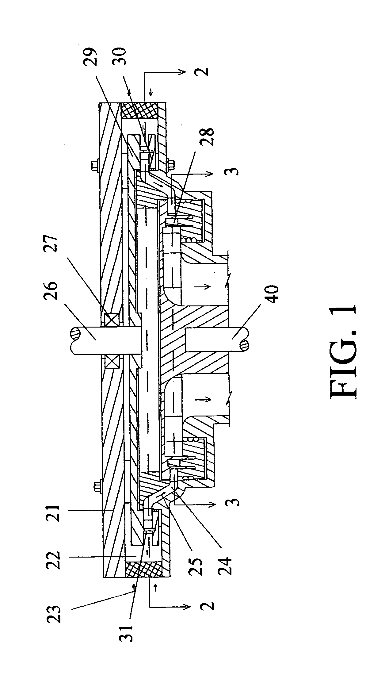
[0020]FIG. 1 is a sectional view in a schematic representation of an exemplary embodiment of a rotary ram-in compressor, in accordance with the present invention.

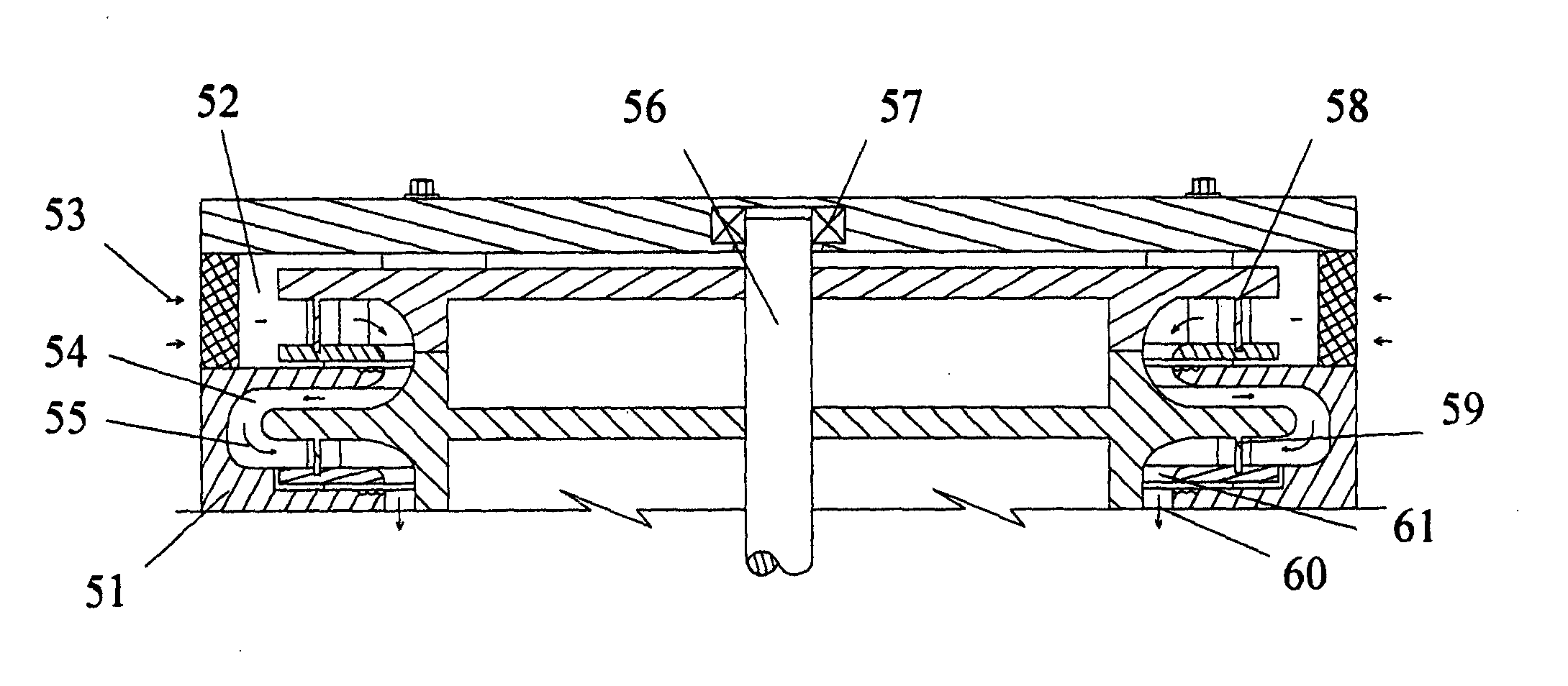
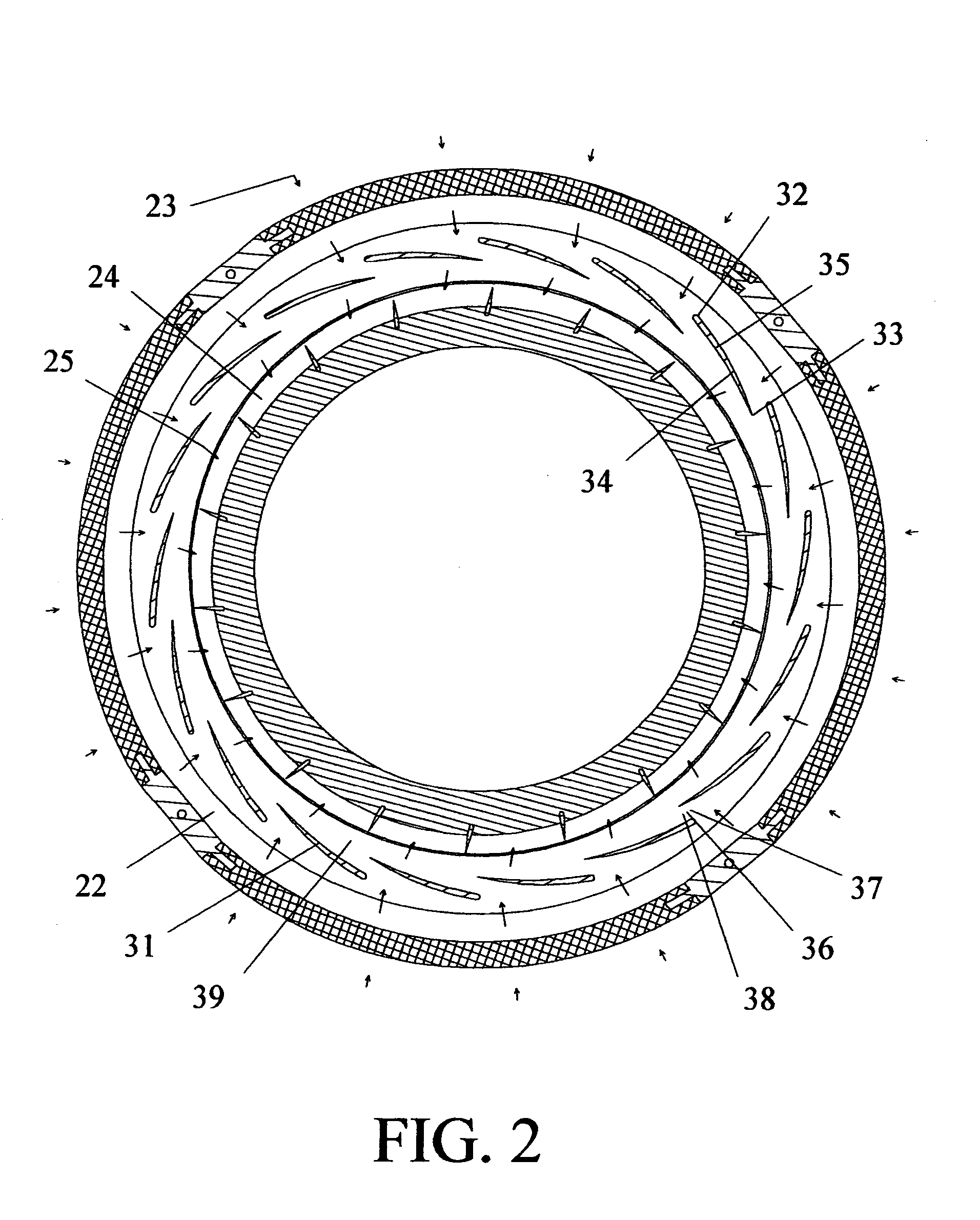
[0021] The main components of the rotary ram-in compressor in this embodiment are a stationary casing (21) having an inlet passage (22) for admission of working gases (23), and a receiver (24) wherein pressurized gases (25) collect; a drive shaft (26) supported for rotation in a given direction inside the casing by an arrangement of bearings (27), and extending to a drive receiving end located outside the casing; and a rotor assembly housed inside the casing and secured for rotation with the drive shaft (26). The rotor assembly comprises a first disk (29) secured for rotation with the drive shaft (26) and lying in a first plane transverse to the rotational axis of the drive shaft; a second disk (30) having a large open center and a widened rim, and lying in a second plane transverse to the rotational axis of the drive shaf...


PUM


Abstract

A rotary ram-in compressor for use in gas turbine engines and the like, having a plurality of vanes attached to discs, with the opposing parts of each two adjacent vanes defining a feeding channel in-between. In operation, working gases are rammed through the feeding channels, followed by positive displacement of the rammed-in gases to a receiver wherein pressurized gases collect. The pressurized gases are actively swept from the receiver by either a successive rotary ram-in compressor or a successive rotary ram compressor.

Description

FIELD OF THE INVENTION [0001] The present invention relates to a positive displacement compressor and, more particularly, to a rotary positive displacement compressor convenient for use in gas turbine engines and the like. DESCRIPTION OF PRIOR ART [0002] Rotary compressors are well known devices, used in several fields to develop a pressure gradient between two points across a stream of working gases. Two main types of rotary compressors are in use, dynamic compressors, i.e., centrifugal flowing, axial flowing, and the combined types, and positive displacement compressors. In dynamic compressors the working gases are accelerated followed by its deceleration within diverging passages, wherein part of its kinetic energy is converted into static pressure rise. In positive displacement compressors the pressure is increased by reducing the specific volume of the gases during their passage through the compressor. [0003] Dynamic Compressors are widely in use in gas turbine and steam engine...

Claims


Application Information

Patent Timeline
Patent Type & Authority Applications(United States)
IPC IPC(8): F01D1/02F01D1/06
CPCF01D1/06
Inventor AWDALLA, ESSAM T.
Owner RRC SGTE TECH
Why Eureka
Try Eureka