Thermal barrier coating resistant to sintering

a technology of thermal barrier coating and sintering, which is applied in the field of thermal barrier coating (tbc), can solve the problems of the combustion turbine engine installed in the land-based power generating plant is also subject to high operating temperature and temperature transient, and is required to operate at full power and at its highest temperatur

Inactive Publication Date: 2005-03-24
THE UNITED STATES AS REPRESENTED BY THE DEPARTMENT OF ENERGY
View PDF0 Cites 10 Cited by
  • Summary
  • Abstract
  • Description
  • Claims
  • Application Information

AI Technical Summary

Benefits of technology

[0015] This invention has the potential to extend the operating temperature capabilities and durability of turbine engines beyond the current state of the art, air plasma spray (APS) 8 wt. % yttrium stabilized zirconia TBC. It involves the deposition of ceramic coatings with horizontal and—predominantly—vertical gaps and the infiltration of these predominantly vertical cracks with a sintering inhibitor. Upon operation at high temperatures, where sintering or closing up of the cracks could occur leading to a loss in strain tolerance, the sintering inhibitor is expected to prevent closure of the vertical cracks. This will allow for maintenance of a strain tolerant TBC to higher surface temperatures and / or extended periods of operation and consequently lead to improved performance. This invention provides a cost-effective alternative to the EB-PVD process.
[0016] The EB-PVD process is a very expensive technique compared to air plasma spraying and this is primarily due to the requirement of a vacuum chamber to deposit the coatings and also the longer processing time required for the complete coverage of the turbine components. A cost-effective process is air plasma spraying and a microstructure with vertical cracks can be obtained by notifying the deposition parameters to yield segmented TBCs. Similar microstructures may also be processed by other coating techniques such as sol-gel and chemical vapor deposition “CVD” techniques. By introducing a sintering inhibitor, the multiphase coating system discussed in this disclosure becomes an economically very competitive thermal barrier coating system for application at high temperatures. Additionally, the selection process for the composition of the base ceramic coating need not be constrained by requirements specific to physical vapor deposition techniques, such as minimum differences in vapor pressure between the constituents of the ceramic composition. With the additional flexibility of utilizing plasma spraying techniques, more complex parts can be handled when compared to EB-PVD coatings.

Problems solved by technology

Although nickel and cobalt based superalloy materials are now used for components in the hot gas flow path, such as combustor transition pieces and turbine rotating and stationary blades, even these superalloy materials are not capable of surviving long term operation at temperatures sometimes exceeding 1000° C.
A combustion turbine engine installed in a land-based power generating plant is also subjected to high operating temperatures and temperature transients, but it may also be required to operate at full power and at its highest temperatures for very long periods of time, such as for days or even weeks at a time.
Prior art insulating systems are susceptible to degradation under such conditions at the elevated temperatures demanded in the most modern combustion turbine systems.
Higher temperatures would then lead to accelerated sintering of cracks and pores in the APS coatings, especially at the surface.
Sintering results in densification of the coating and can lead to its early spallation, due to its reduced capacity to accommodate thermal cycling.
The above-mentioned patents articles, however, do not address the possibility of sintering the vertical cracks and the subsequent loss in strain compliance with increasing operating temperatures.
The EB-PVD process is a very expensive technique compared to air plasma spraying and this is primarily due to the requirement of a vacuum chamber to deposit the coatings and also the longer processing time required for the complete coverage of the turbine components.

Method used


Image

  • Thermal barrier coating resistant to sintering
  • Thermal barrier coating resistant to sintering
  • Thermal barrier coating resistant to sintering

Examples


Embodiment Construction

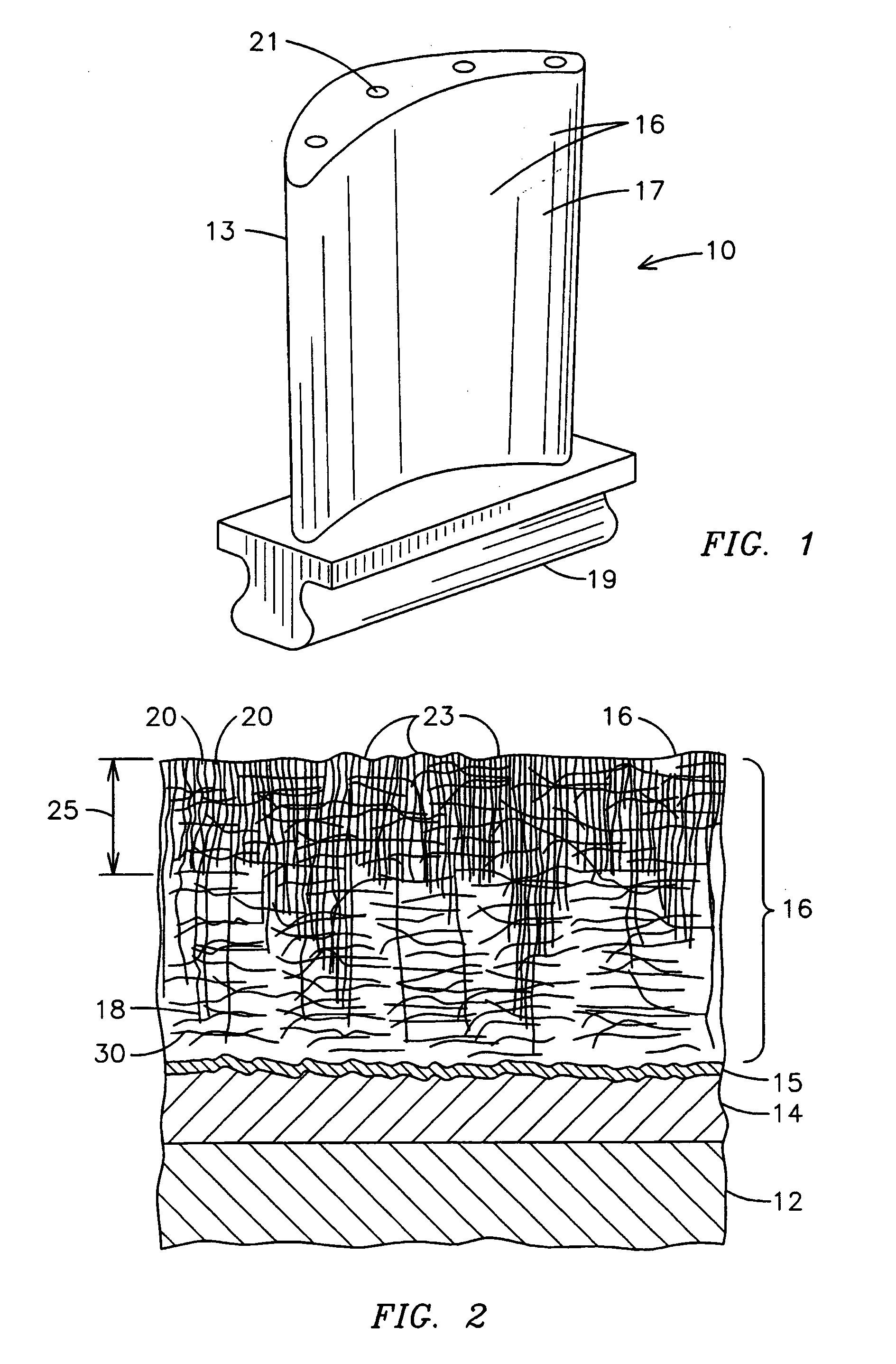
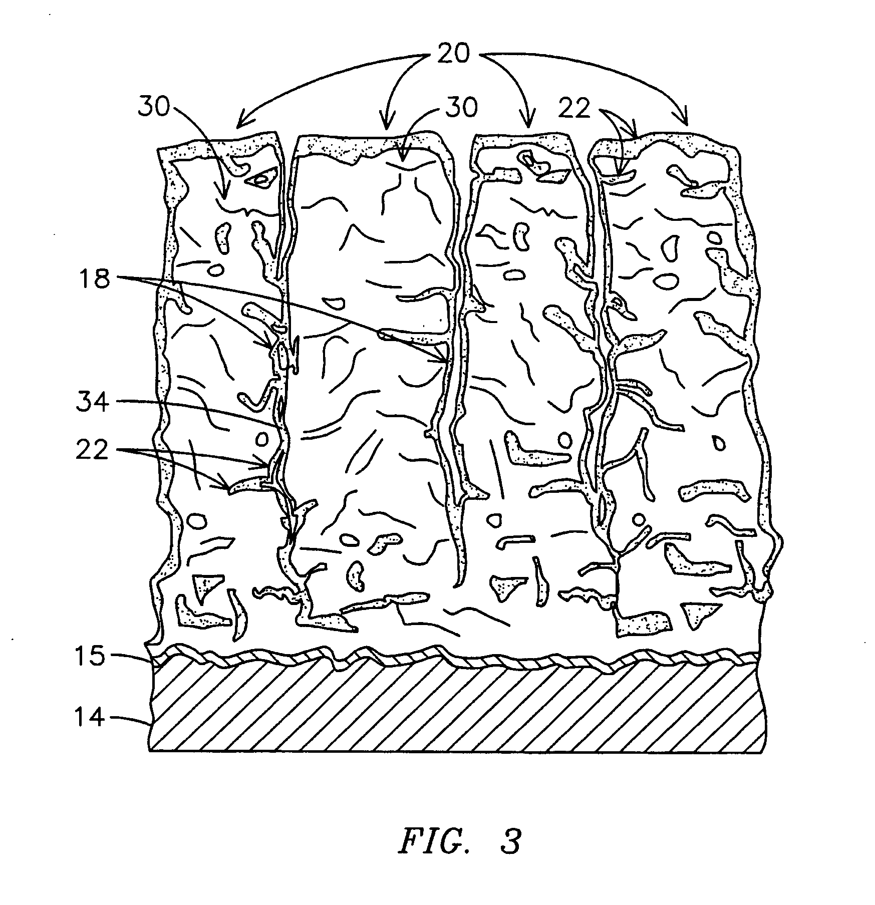
[0029] When prior art thermal barrier coating systems are exposed to the high temperature environment of the hot gas flow path of a land-based combustion turbine power plant, one of the reasons for failure of the thermal barrier coating is sintering of the ceramic TBC and consequent loss in strain tolerance. A current state-of-the-art thermal barrier coating is yttria stabilized zirconia (YSZ). The YSZ may be applied in this invention by thermal spray processes such as new and improved air plasma spray APS, inductively coupled plasma processes, high power and high velocity plasma processes, or by vapor deposition processes such as chemical vapor deposition CVD, MOCVD, or by ceramic processing techniques such as sol-gel, all now well known in the art. These techniques can provide a predominantly vertical (in relation to the substrate) columnar microstructure at the outside surface of TBCs and also create a series of submicron sized horizontal cracks within the YSZ layer intersecting ...


PUM

PropertyMeasurementUnit
temperatureaaaaaaaaaa
thicknessaaaaaaaaaa
widthaaaaaaaaaa

Abstract

A device (10) is made, having a ceramic thermal barrier coating layer (16) characterized by a microstructure having gaps (18) with a sintering inhibiting material (22) disposed on the columns (20) within the gaps (18). The sintering resistant material (22) is stable over the range of operating temperatures of the device (10), is not soluble with the underlying ceramic layer (16) and is applied by a process that is not an electron beam physical vapor deposition process. The sintering inhibiting material (22) has a morphology adapted to improve the functionality of the sintering inhibiting material (22), characterized as continuous, nodule, rivulet, grain, crack, flake and combinations thereof and being disposed within at least some of the vertical and horizontal gaps.

Description

CROSS-REFERENCE TO RELATED APPLICATION [0001] This application is a continuation-in-part application of U.S. Ser. No. 09 / 640,073 filed Aug. 17, 2000, which is a continuation-in-part of U.S. Pat. No. 6,203,927, filed Feb. 5, 1999.GOVERNMENT RIGHTS STATEMENT [0002] This invention was conceived under United States Department of Energy Contract DE-FC02-00CH11048. The United States Government has certain rights hereunder.FIELD OF THE INVENTION [0003] This invention relates generally to the field of thermal barrier coatings (TBC), and more particularly to a thermal barrier coating for very high temperature applications, such as combustion turbine engines. In particular, this invention relates to the field of multi-layer ceramic thermal barrier coatings resistant to sintering damage used for coating superalloy components of a combustion turbine. These TBCs are applied by inexpensive processes selected from the group consisting of: ceramic processing techniques, such as sol-gel techniques; ...

Claims


Application Information

Patent Timeline
Patent Type & Authority Applications(United States)
IPC IPC(8): C23C4/18C23C14/08C23C14/58C23C16/40C23C16/56C23C28/00C23C28/04C23C30/00F01D5/28
CPCY02T50/67Y10T428/26C23C14/083C23C14/58C23C14/5846C23C16/403C23C16/56C23C28/042C23C28/321C23C28/3215C23C28/345C23C28/3455C23C30/00F01D5/288F05C2201/0463F05C2201/0466F05D2300/21F05D2230/90F05D2300/611Y10T428/12618Y10T428/24471Y10T428/12611C23C4/18Y02T50/60
Inventor SUBRAMANIAN, RAMESHSETH, BRIG B.
Owner THE UNITED STATES AS REPRESENTED BY THE DEPARTMENT OF ENERGY
Why Eureka
Try Eureka