Method of forming a package for MEMS-Based fuel cell

a fuel cell and fuel cell technology, applied in the field of forming a package for mems-based fuel cells, can solve the problems of excessive weight, size, cost, and limited mission duration of rechargeable and primary portable power sources

Active Publication Date: 2005-03-24
LAWRENCE LIVERMORE NAT SECURITY LLC
View PDF5 Cites 24 Cited by
  • Summary
  • Abstract
  • Description
  • Claims
  • Application Information

AI Technical Summary

Problems solved by technology

Present rechargeable and primary portable power sources hav...

Method used


Image

  • Method of forming a package for MEMS-Based fuel cell
  • Method of forming a package for MEMS-Based fuel cell
  • Method of forming a package for MEMS-Based fuel cell

Examples


Embodiment Construction

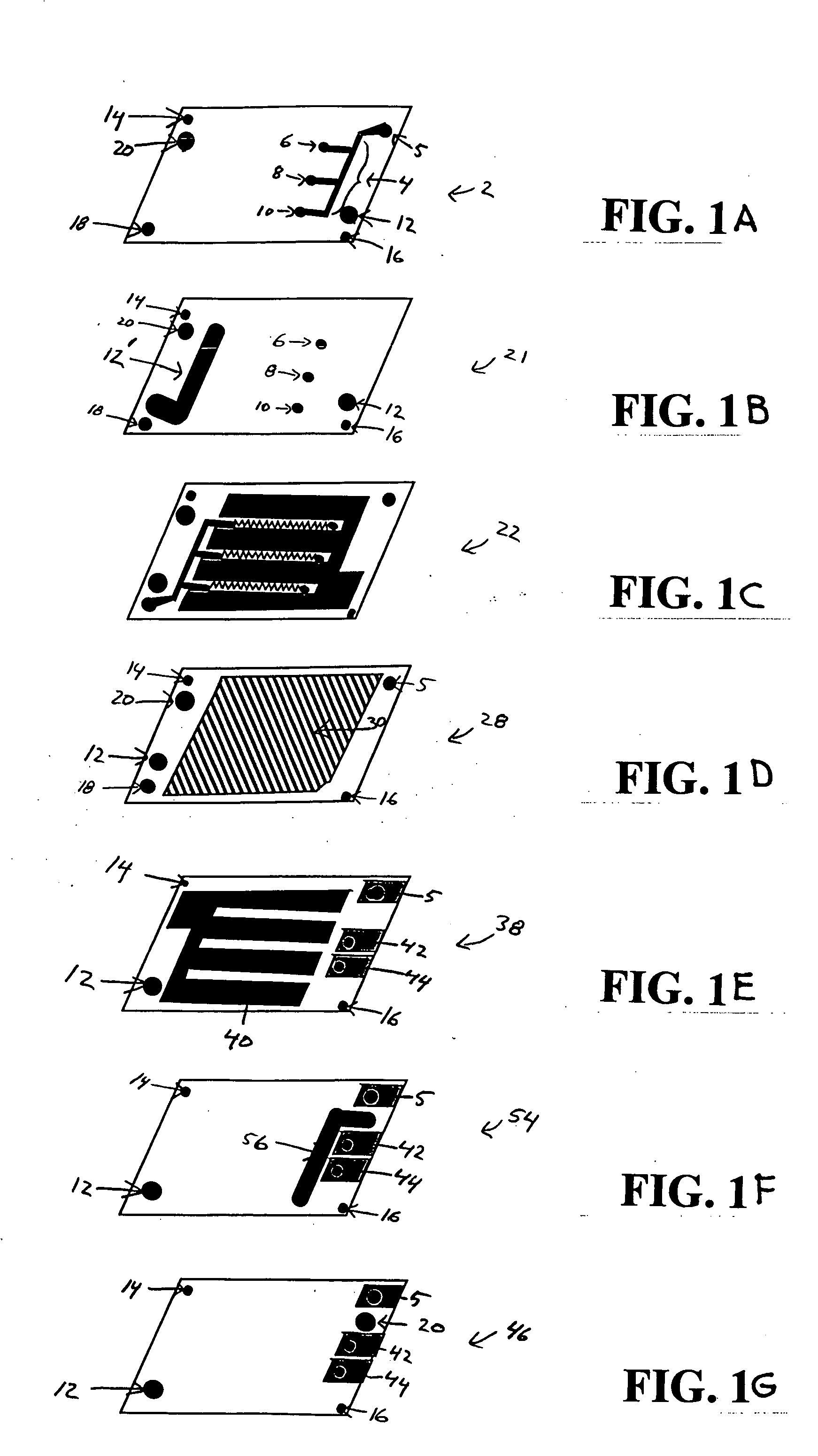
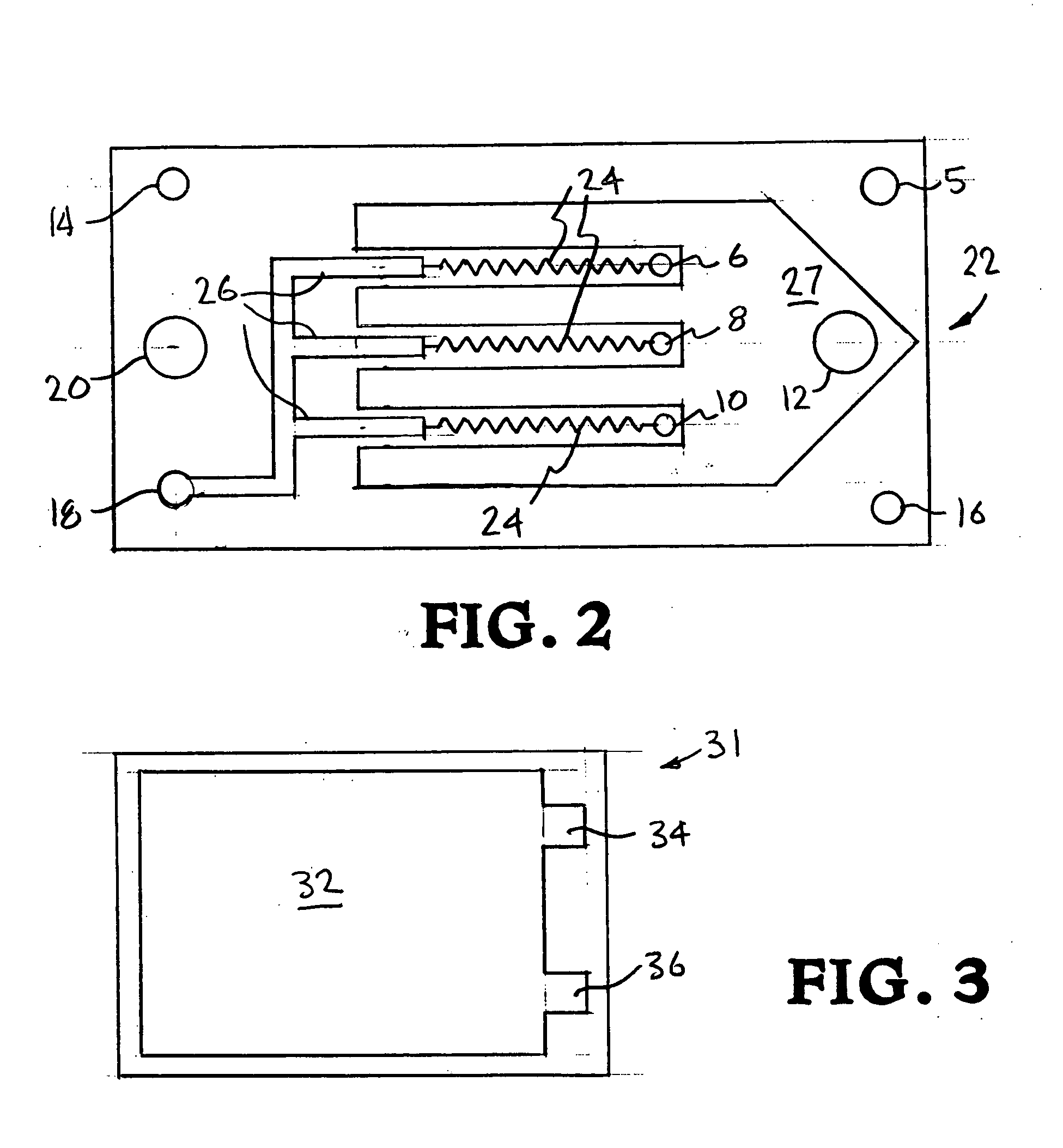
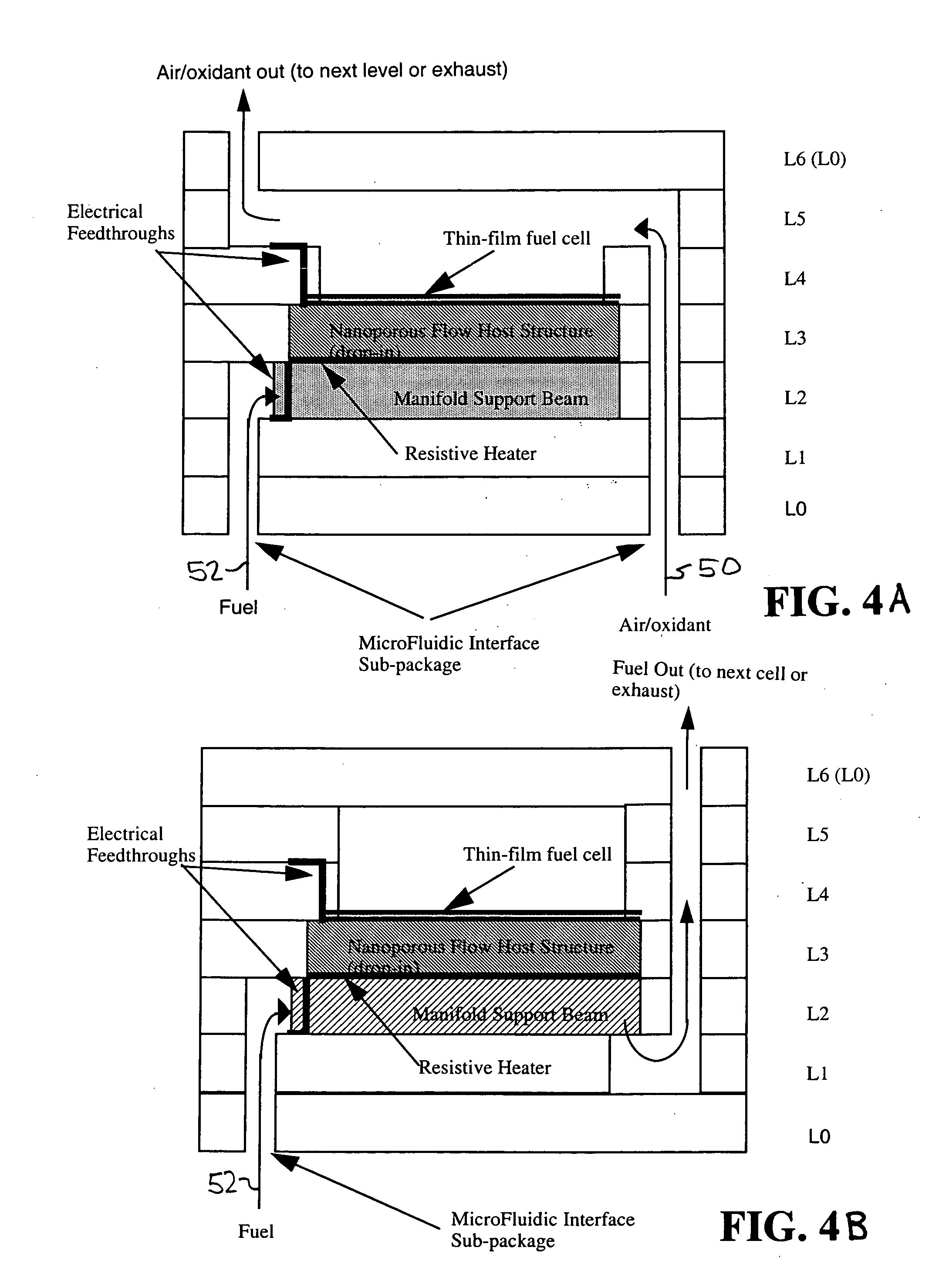
[0018] The invention herein describes a method of forming a package for a miniature fuel cell device. Illustrated in FIGS. 1A-1G is a preform layer of a seven layer fuel cell package. The package can be fabricated from a Low Temperature Co-fired Ceramic (LTCC), i.e., a ceramic green tape preform, such as Dupont 951 Green Tape, or a plastic or polymer preform, such as Dupont Kapton or Sylgard silicone. Methods to form the preform layers include laser cutting, injection molding, or extrusion molding of the ceramic or plastic.

[0019] Referring to FIG. 1A, the first layer of the package, a fuel reservoir interface 2, is fabricated from a ceramic green tape, molded ceramic, or a plastic preform. Fuel reservoir interface 2 comprises a resistive heater current input 4 having three electrical leads 6, 8, and 10, a fuel flow passage 12, a left side alignment pin 14, a right side alignment pin 16, and a grounded resistive heater feedthrough 18. Fuel reservoir interface 2 may also comprise an ...


PUM

PropertyMeasurementUnit
Temperatureaaaaaaaaaa
Thicknessaaaaaaaaaa
Thicknessaaaaaaaaaa

Abstract

A MEMS-based fuel cell package and method thereof is disclosed. The fuel cell package comprises seven layers: (1) a sub-package fuel reservoir interface layer, (2) an anode manifold support layer, (3) a fuel/anode manifold and resistive heater layer, (4) a Thick Film Microporous Flow Host Structure layer containing a fuel cell, (5) an air manifold layer, (6) a cathode manifold support structure layer, and (7) a cap. Fuel cell packages with more than one fuel cell are formed by positioning stacks of these layers in series and/or parallel. The fuel cell package materials such as a molded plastic or a ceramic green tape material can be patterned, aligned and stacked to form three dimensional microfluidic channels that provide electrical feedthroughs from various layers which are bonded together and mechanically support a MEMS-based miniature fuel cell. The package incorporates resistive heating elements to control the temperature of the fuel cell stack. The package is fired to form a bond between the layers and one or more microporous flow host structures containing fuel cells are inserted within the Thick Film Microporous Flow Host Structure layer of the package.

Description

CROSS-REFERENCE TO RELATED APPLICATION [0001] This application is a divisional of application Ser. No. 09 / 967,145 filed on Sep. 28, 2001 entitled “Method of Forming a Package for MEMS-Based Fuel Cell”[0002] The United States Government has rights in this invention pursuant to Contract No. W-7405-ENG-48 between the United States Department of Energy and the University of California for the operation of Lawrence Livermore National Laboratory.BACKGROUND OF THE INVENTION [0003] Portable power sources of various types have been under development for many years. A serious need exists for portable power sources with significantly higher power density, longer operating lifetime, and lower cost. Present rechargeable and primary portable power sources have excessive weight, size, and cost with limited mission duration. For example, batteries covering power range from 1-200 Watts have specific energies ranging from 50-250 Whr / Kg, which represents two to three hours of operation for a variety o...

Claims


Application Information

Patent Timeline
IPC IPC(8): H01M4/86H01M4/88H01M8/02H01M8/04H01M8/24
CPCH01M8/04007H01M8/241H01M8/247Y02E60/50Y10T29/49112Y10T29/53135Y10T156/1057Y10T29/49108Y10T29/49114Y10T29/4911H01M8/2432H01M8/02H01M8/24H01M8/2404
Inventor MORSE, JEFFREY D.JANKOWSKI, ALAN F.
Owner LAWRENCE LIVERMORE NAT SECURITY LLC
Why Eureka
Try Eureka