Low-temperature co-fired ceramic substrate and preparation method thereof

A technology of low-temperature co-fired ceramics and ceramics, which is applied in the field of functional ceramic materials, and can solve the problems of high surface roughness of green ceramic belts, unsuitability for ceramic powder, and high residue of pyrolytic carbon, so as to achieve strong processing adaptability and controllability High, smooth surface effect

Inactive Publication Date: 2021-09-17
SHANGHAI INST OF CERAMIC CHEM & TECH CHINESE ACAD OF SCI
View PDF7 Cites 8 Cited by
  • Summary
  • Abstract
  • Description
  • Claims
  • Application Information

AI Technical Summary

Problems solved by technology

However, commonly used polyvinyl butyral (PVB) binders often lead to high slurry viscosity, low green tape strength, high surface roughness, and high pyrolytic carbon residues. Sintering under an oxygen atmosphere, not suitable for ceramic powders sintered under a reducing atmosphere
In particular, LTCC ceramic powder usually contains borosilicate glass, which is sensitive to the aldehyde group of PVB and easily causes slurry flocculation

Method used


Image

  • Low-temperature co-fired ceramic substrate and preparation method thereof
  • Low-temperature co-fired ceramic substrate and preparation method thereof
  • Low-temperature co-fired ceramic substrate and preparation method thereof

Examples


preparation example Construction

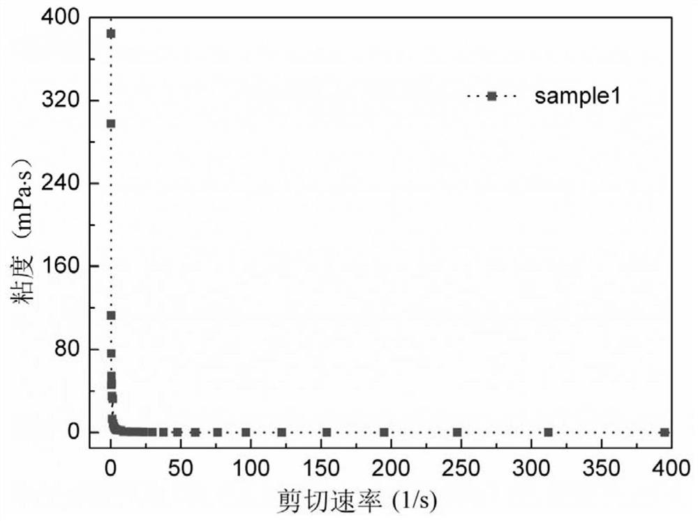
[0045] As a detailed example of preparation of ceramic casting slurry, it includes: (1) mixing raw materials including ceramic powder, solvent and dispersant, and then performing primary ball milling. The mass ratio of the mixture of ceramic powder, solvent and dispersant to grinding body may be 1:(3-4). The rotating speed of the initial ball milling can be 50-90 rpm, and the time can be 4-12 hours. (2) Add binder and plasticizer to the slurry obtained after primary ball milling, and perform secondary ball milling. The rotating speed of the secondary ball milling can be 60-120 rpm, and the time can be 12-24 hours. (3) Vacuum defoaming the slurry after secondary ball milling to obtain the ceramic casting slurry. Wherein, the parameter of vacuum defoaming can be -30~-42kPa.

[0046] The ceramic casting slurry is tape-casted to prepare a ceramic tape-cast green tape. The thickness of the ceramic cast green tape obtained in the present invention may be 20-200 microns, preferab...

Embodiment 1

[0053] This embodiment provides a processing method for electronic ceramic casting slurry, the processing method comprising the following steps:

[0054] (1) Ca-B-Si-O system (42%CaO-26%B 2 o 3 -32% SiO2 2 ) Ceramic powder, solvent, and dispersant are first ball milled for 6 hours. The mass ratio of the raw material to the grinding body is 1:3. The solvent used is butanone / ethanol, and the amount added to the casting slurry is 80% of the mass of the ceramic powder. The dispersant is MALIALIM (AKM0531, Japan), and its addition is 1% of the mass of the ceramic powder;

[0055] (2) Adding a binder into the ball milling jar, and performing a second ball milling for 16 hours to obtain a ceramic casting slurry. The binder used is polymethacrylate (M6003, Japan), and its addition amount is 12.5% ​​of the mass of the ceramic powder. The plasticizer is butyl benzyl phthalate (BBP), and its addition amount is 2.5% of the mass of the ceramic powder.

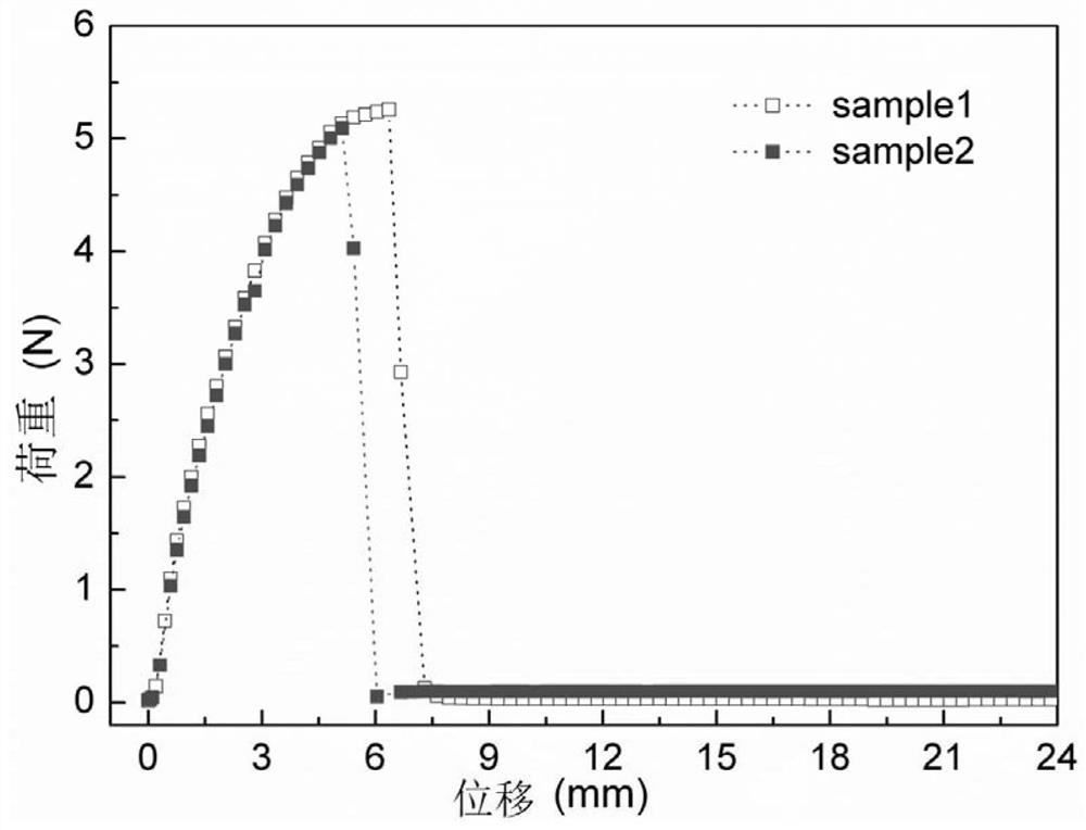
[0056] The ceramic tape casti...

Embodiment 2

[0065] Refer to Example 1 for the preparation process of the electronic ceramic casting slurry in Example 2, except that the content of polymethacrylate is 5 wt%. Using the ceramic casting slurry prepared in this embodiment, a ceramic green tape with a thickness of 120 microns was cast on a fully automatic casting machine. Among them, the ceramic raw porcelain has partial cracks, which cannot be completely peeled off from the PET carrier film, and the tensile strength and flexibility are also poor.


PUM

PropertyMeasurementUnit
particle sizeaaaaaaaaaa
thicknessaaaaaaaaaa
tensile strengthaaaaaaaaaa

Abstract

The invention relates to a low-temperature co-fired ceramic substrate and a preparation method thereof. The preparation method of the low-temperature co-fired ceramic substrate comprises the following steps: (1) mixing 40-60 wt% of ceramic powder, 30-50 wt% of a solvent, 5-15 wt% of a binder and 0.2-2 wt% of a dispersant to obtain ceramic tape casting slurry, the binder being polymethacrylate; (2) carrying out tape casting on the obtained ceramic tape casting slurry to obtain a ceramic casting green tape; and (3) placing the obtained ceramic casting green tape in an air atmosphere or an oxygen-free atmosphere, discharging glue at 380-450 DEG C, and sintering the material to obtain the ceramic substrate, or printing at least one of the Cu electrode and the Ni electrode on the ceramic casting green tape and then placing the green tape in the oxygen-free atmosphere, carrying out glue discharging at the temperature of 380-450 DEG C, and sintering the green tape to form the low-temperature co-fired ceramic substrate.

Description

technical field [0001] The invention relates to a low-temperature co-fired ceramic substrate and a preparation method thereof, in particular to a method for preparing a low-temperature co-fired ceramic substrate with a polymethacrylate binder-based ceramic casting green tape, and belongs to the field of functional ceramic materials. Background technique [0002] In recent years, as wireless communication, aerospace and automotive fields have increasingly high requirements for equipment diversity and system reliability, it is inevitable for electronic components to develop in the direction of miniaturization, high frequency, multi-function and integration. trend. As the package size becomes smaller and smaller, the circuit group density and system stability requirements increase again and again, all these make the modularization and high integration of multi-chips, circuits and components an inevitable trend and choice. If some passive components can be integrated into the s...

Claims


Application Information

Patent Timeline
Patent Type & Authority Applications(China)
IPC IPC(8): C04B35/622C04B35/638C04B35/64C04B35/634C04B35/22C04B35/582C04B35/468C04B35/569C04B41/88
CPCC04B35/622C04B35/638C04B35/64C04B35/63424C04B35/22C04B35/581C04B35/4682C04B35/565C04B41/88C04B41/5127C04B41/5144C04B2235/5445C04B2235/3409C04B2235/6583C04B2235/658C04B2235/6582C04B41/4539C04B41/4578C04B41/0072
Inventor 吕潭刘峰张发强刘志甫
Owner SHANGHAI INST OF CERAMIC CHEM & TECH CHINESE ACAD OF SCI
Why Eureka
Try Eureka