Battery pack manufacturing method

a manufacturing method and battery technology, applied in the field of batteries, can solve the problems of high manufacturing cost of resin molding dies used in pack cases, battery packs using pack cases are not suited to portable electronic equipment that are re-modeled, and fire or explosion of batteries, so as to prevent short circuits or leakage, excellent moisture resistance properties

Inactive Publication Date: 2005-03-24
PANASONIC CORP
View PDF0 Cites 54 Cited by
  • Summary
  • Abstract
  • Description
  • Claims
  • Application Information

AI Technical Summary

Benefits of technology

[0016] To achieve the above object, a battery pack according to a first aspect of the present invention comprises a rechargeable battery and a substrate at least having an external terminal that are electrically connected and united by solidified molded resin; and a resin mold member partly covering the battery and the substrate that is at least formed with an opening for exposing the external terminal to the outside. The resin used for uniting the rechargeable battery and the substrate is a resin that is moldable at a relatively low temperature so as not to cause adverse effects on the rechargeable battery or electronic components, which is not suitably applied, in terms of hardness and appearance, to parts that are exposed to the outside. The parts that will be on the outside are thus covered with another resin mold member so as to provide an ideal covering for the battery pack that uses a resin mold.
[0018] In the above structure, the upper resin mold and the lower resin mold may be coupled together by connection pieces that run along the sides of the battery, so that the battery pack has an enhanced rigidity because of the coupled upper and lower resin molds and the winding sheet wound around the connection pieces.
[0019] The upper and lower resin molds and the connection pieces may be integrally molded such that the connection pieces is bendable at right angles at hinges formed therewith, so as to collectively mold these parts and facilitate management or assembly of the components.
[0031] The outer covering provided to the intermediate product includes the following that are formed by a secondary molding process: an upper mold covering one surface of the circuit substrate where the external terminal is formed and the sealing plate of the rechargeable battery while exposing at least the external terminal to the outside; a lower mold formed on the bottom face of the rechargeable battery to a predetermined height; and a connecting mold part that couples the upper mold and the lower mold along the shorter sides of the rechargeable battery. A sheet is wound around to cover the side faces of the battery, part of the side faces of the upper mold and the lower mold, and the connecting mold part. Thereby, a thin battery pack is obtained, whose thickness is the sum of the thickness of the rechargeable battery and that of the sheet. The connecting mold part should preferably have a cross section that conforms to part of a rectangle that surrounds the circular arcs at both ends of the oval cross section of the rechargeable battery, so that the width of the battery pack will be the sum of the width of the rechargeable battery and the thickness of the sheet, i.e., there will be no unnecessary increase in the size of the battery. Also, if the connecting mold part is formed only on one side of that rectangle surrounding the circular arcs, then the battery pack will have an asymmetric cross section, which will restrict the direction in which it is loaded into equipment, and the circular arc side of the battery pack will fit in a rounded shape formed at a corner of a battery accommodation case inside the equipment.
[0033] Further, the outer covering is formed of resin such as to cover the entire surface of the intermediate product except for predetermined parts including the external terminal, so that the intermediate product is covered in an air / liquid tight manner and the battery pack has excellent moisture resistance properties.
[0034] Parts of the dies used for the primary and secondary molding that will make contact with exposed active parts of the object to be resin packed or the intermediate product should preferably be provided with an insulation coating, so as to prevent short circuits or leaks during the resin molding or the process of providing the outer covering.

Problems solved by technology

A temperature rise in the battery causes a rapid build-up of gas pressure inside resulting from reactions between positive electrode active materials and electrolyte, or from evaporation or decomposition of electrolyte, which may result in fire or explosion of the battery.
However, battery packs using pack cases are not suited to portable electronic equipment that are re-modeled in short cycles, because the manufacturing cost of molding dies used in the resin molding of pack cases tends to be high, and the time required for designing new molding dies is relatively long.
Moreover, battery packs with resin-molded outer cases also have limitations in making portable electronic equipment smaller and thinner because of the limitations on the moldable thickness in the resin molding process.
This external connection structure will present no problem if the equipment is relatively large and offers enough space for accommodating the battery, but the battery packs to which the invention is directed are primarily designed for small equipment where battery accommodation space is scarce, and therefore cannot adopt such connection structure.
If the dimensional precision is low, the contact resistance between the equipment-side connection terminals and external terminals becomes high, leading to malfunctions such as contact failure and voltage drop.
These structures, however, require an increased accommodation space for the battery pack on the equipment side and a larger number of components for the connection of the battery pack, prohibiting the miniaturization of such equipment.
Namely, these structures are hardly applicable to small electronic equipment such as mobile phones that have limited space.
Hot melt resin, however, has a low hardness after curing and is not suitable as an outer member exposed to the outside because it is susceptible to scratches and contaminant adhesions.

Method used


Image

  • Battery pack manufacturing method
  • Battery pack manufacturing method
  • Battery pack manufacturing method

Examples


Embodiment Construction

[0061] Preferred embodiments of the present invention will be hereinafter described with reference to the accompanying drawings for an understanding of the invention. It should be understood that the following embodiments of the invention are merely given as examples and should not limit the technical scope of the invention.

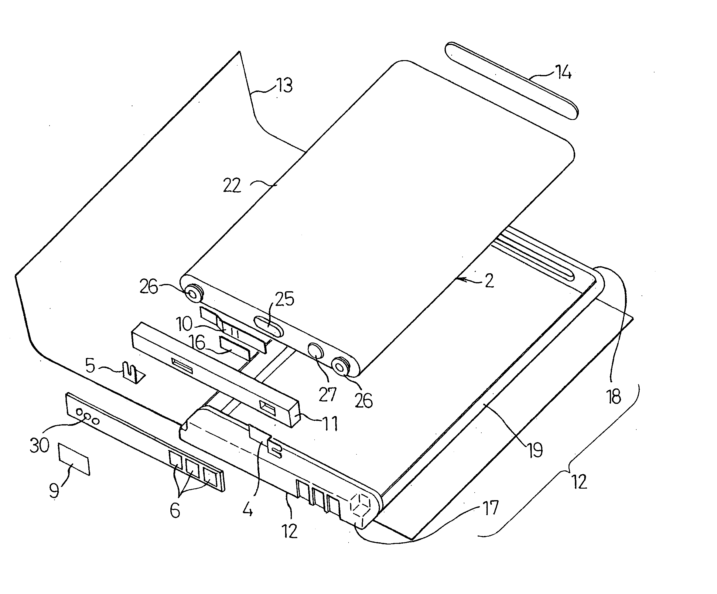
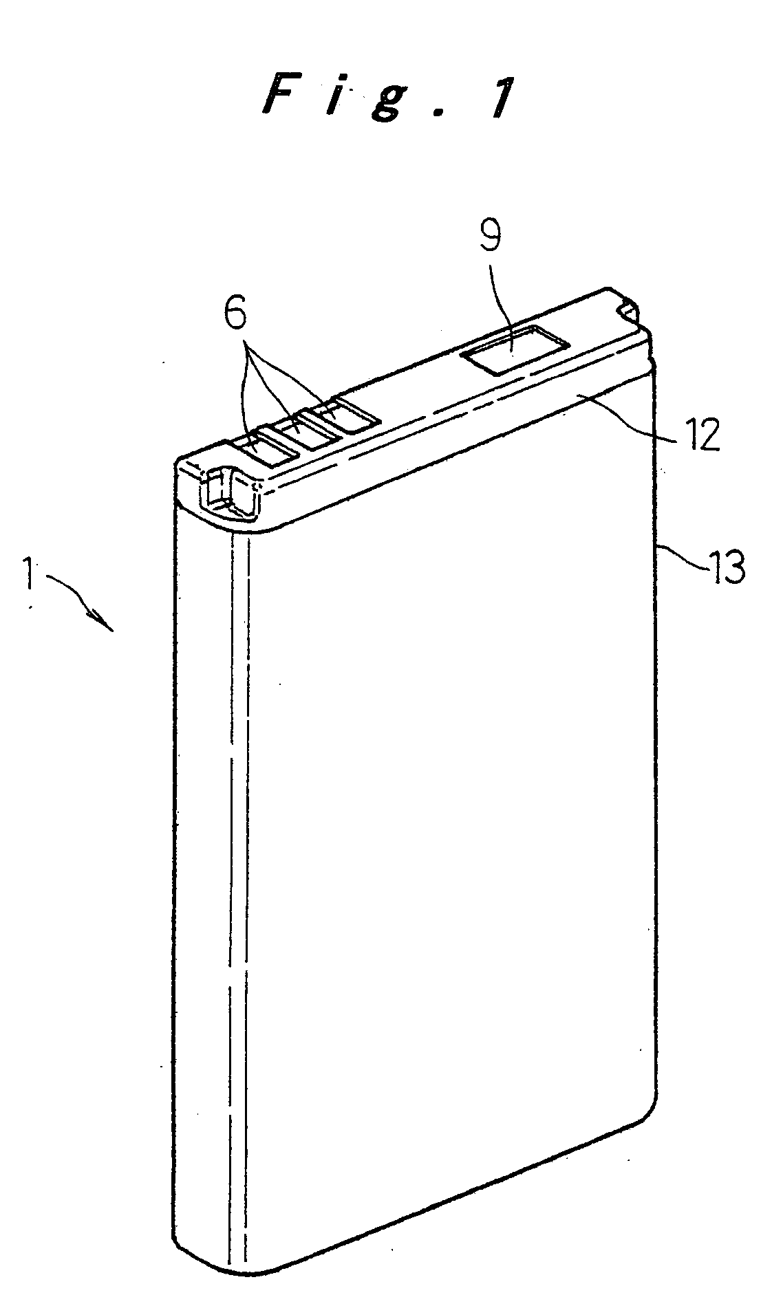
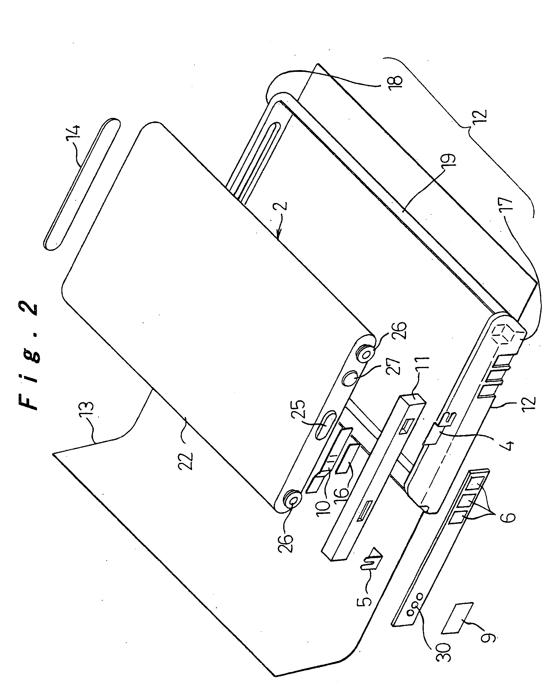
[0062] The present embodiment shows one example of a battery pack employing a flat prismatic lithium ion rechargeable battery applied to a mobile phone. Battery packs for mobile phones need to be small, light-weight, and thin, and in addition, they are desired to have a high energy density in accordance with high functionality, a high mechanical strength to withstand impacts caused by a falling accident which is inevitable with portable equipment, a structure that does not allow easy disassembling, and safety features for protecting the rechargeable battery from short circuits, overcharge, and high temperature. The battery pack described below satisfies all thes...


PUM

PropertyMeasurementUnit
temperatureaaaaaaaaaa

Abstract

A rechargeable battery (2) and a circuit substrate (3) are connected by lead plates (4, 5) and united by a primary mold (11) that is formed by filling resin therebetween, after which a secondary mold (12) is formed on the outer face by filling resin at necessary locations and a winding sheet (13) is wound around the periphery, thereby forming a battery pack.

Description

TECHNICAL FIELD [0001] The present invention relates to a battery pack in which constituent elements are united by filling with resin to reduce the size thereof and improve the rigidity thereof so that it is suitable as a power source for portable electronic equipment, and a manufacturing method thereof. BACKGROUND ART [0002] With the remarkable development of small, thin, and high-functionality portable electronic equipment such as mobile phones and PDAs, there is a growing demand for smaller, thinner, and high-capacity batteries as their power source. Lithium ion rechargeable batteries can be designed small and high-capacity, and in particular, flat prismatic types are suitable in making the equipment thinner; they have therefore been increasingly used as the repeatedly usable rechargeable battery for portable electronic equipment. [0003] Because lithium ion rechargeable batteries have high energy density and contain a flammable organic solvent as electrolyte, it is essential to t...

Claims


Application Information

Patent Timeline
Patent Type & Authority Applications(United States)
IPC IPC(8): H01M10/04H01M50/593
CPCH01M2/1066H01M2/1241Y10T29/49108H01M2/348Y10T29/4911H01M2/34Y02E60/10H01M50/3425H01M50/581Y02P70/50H01M50/593H01M50/209
Inventor KOZU, KATSUMIISHIMARU, TAKESHIOSAWA, YOSHIKIKATAOKA, SATOSHIMORI, IICHIROTORIYAMA, KOICHIMIZUTA, MASAHIROCHIKADA, TATSUHISA
Owner PANASONIC CORP
Why Eureka
Try Eureka