Structure and method for placement, sizing and shaping of dummy structures

a technology of dummy structures and structures, applied in the direction of cad circuit design, semiconductor/solid-state device testing/measurement, instruments, etc., can solve the problems of device degradation, process non-uniformity, and reduce yield, so as to improve yield and reliability in the fabrication of chips

Inactive Publication Date: 2005-03-24
INFINEON TECH AG
View PDF8 Cites 14 Cited by
  • Summary
  • Abstract
  • Description
  • Claims
  • Application Information

AI Technical Summary

Benefits of technology

According to another aspect of the invention, the location, size, and / or shape of a dummy structure that are added to a material layer is selected on the basis of pattern density of neighboring functional features. With the addition of dummy structures to the layout of a material layer of a substrate, it is possible to improve yield and reliability in the fabrication of chips. In an embodiment of the invention, a material layer of a substrate comprises a number of functional structures. In order to control pattern density during fabrication, dummy fill structures of different sizes are added to the material layer at different distances from the functional structures of the material layer. In particular, the placement and size and shape of the dummy structures are determined as a function of a distance to, and density of, the functional structure(s) in the material layer of the substrate.

Problems solved by technology

A problem occurs when a resist layer contains features of different densities and sizes.
Again, variation in the size and density of features can cause the concentration of reactants and reaction products to vary, thus making the process nonuniform.
Failure to achieve such goals can hinder the function of features in a material layer and / or hinder subsequent processing in a manner that can cause device degradation and reduce yields.
Unfortunately, the above techniques still have limitations with respect to improving the yield and reliability of chip fabrication.

Method used


Image

  • Structure and method for placement, sizing and shaping of dummy structures
  • Structure and method for placement, sizing and shaping of dummy structures
  • Structure and method for placement, sizing and shaping of dummy structures

Examples


Embodiment Construction

Other than the inventive concept, the apparatus and methods for fabricating chips are well-known and are not described further herein. Also, like numbers on different figures represent similar elements.

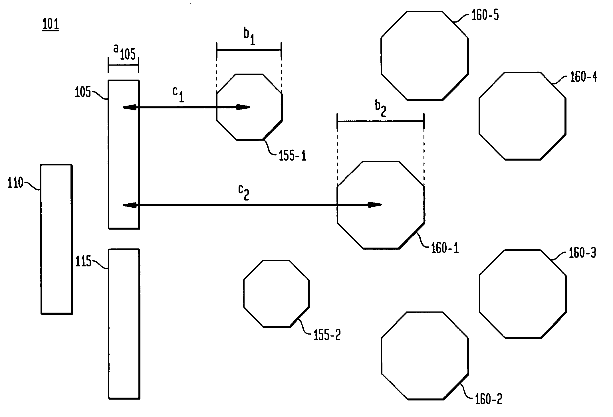
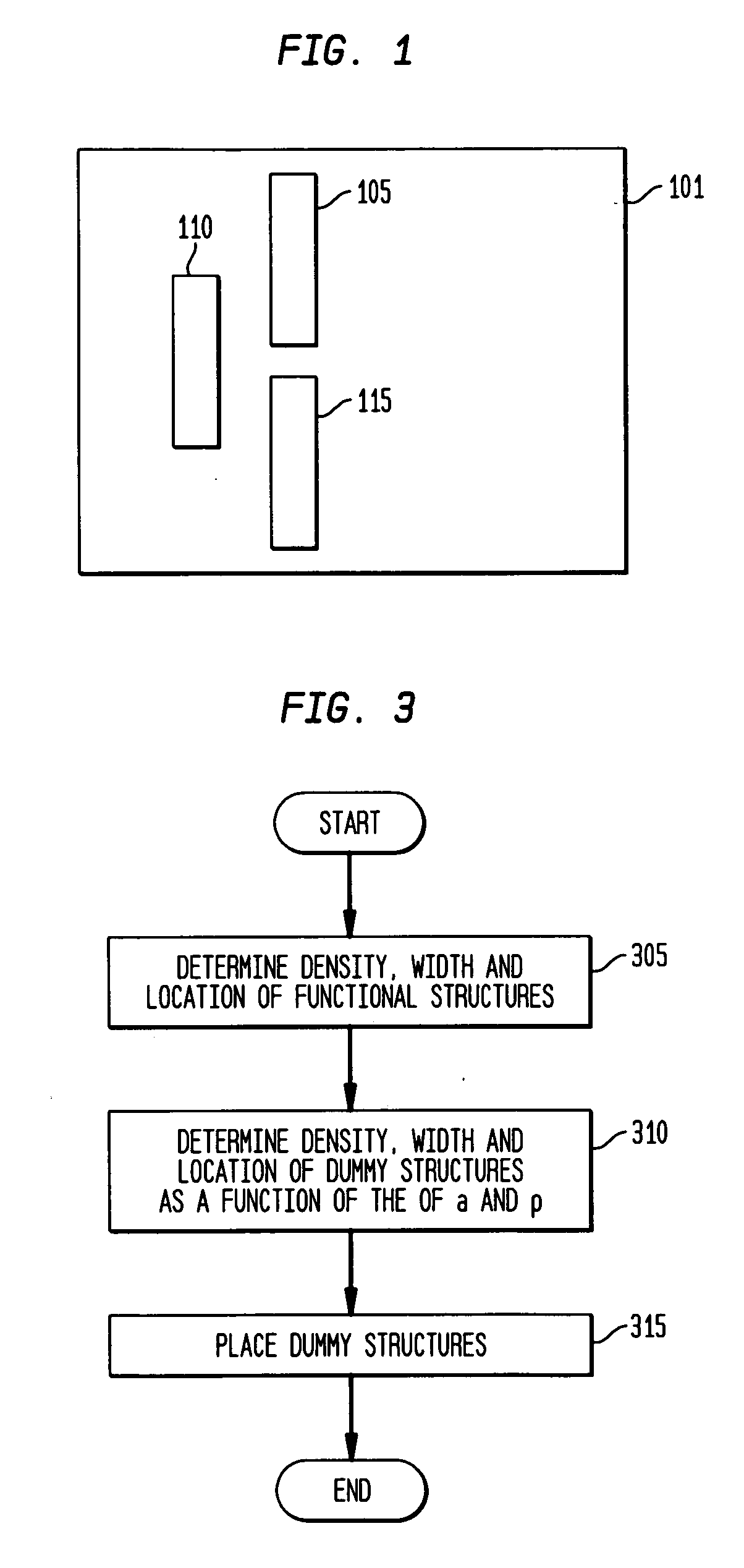
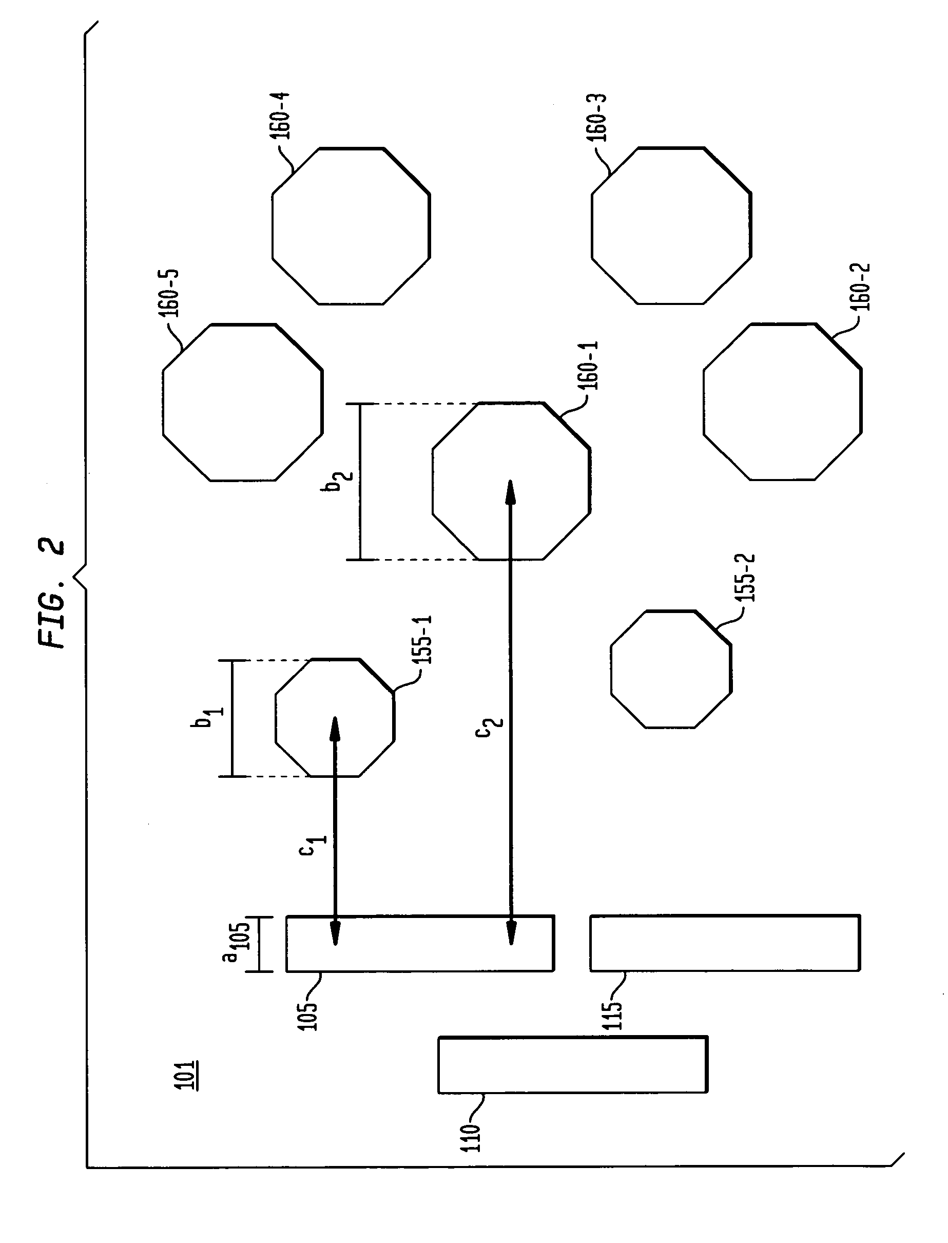
A top view of a representative layer 101 of an illustrative substrate 100 or formed on such substrate 100 is shown in FIG. 1. Illustratively, substrate 100 can be a semiconductor wafer, or can be any one of many different types of substrates on which processing is performed to pattern one or more layers thereof or formed thereon in the fabrication of microelectronic devices, MEMs and associated packaging. As defined herein, “layer” can be a layer formed on a substrate and can be portion or all of the substrate itself. Substrate 100 comprises three functional areas: 105, 110 and 115 arranged on layer 101. These functional areas represent raised areas of a layer 101 and may include, but are not limited to, one or more of the following: active elements, passive elements, and conductiv...


PUM


Abstract

A material layer on a substrate being processed, e.g. to form chips, includes one or more functional structures. In order to control pattern density during fabrication of the chip, dummy fill structures of different sizes and shapes are added to the chip at different distances from the functional structures of the material layer. In particular, the placement, size and shape of the dummy structures are determined as a function of a distance to, and density of, the functional structures of the material layer.

Description

BACKGROUND OF THE INVENTION The present invention relates to microelectronic devices and micro-mechanical and micro-electromechanical devices (either type or both types hereinafter, “MEMs”), and more particularly, to a structure and method of providing dummy structures in a layer of material of a substrate during the fabrication of microelectronic devices and MEMs to achieve more uniform developer solution rates, etching rates, and rate at which the height of features of a layer are reduced during planarization processes such as chemical mechanical polishing (CMP). In the fabrication of microelectronic devices of integrated circuits (ICs) and MEM dies (ICs and MEM dies also referred to herein as “chips”), it is important that certain processes be conducted at uniform rates across the surface of a substrate or wafer on which the chips are fabricated. This is needed despite the fact that the size of layout features and their density may vary from one point to another on the substrat...

Claims


Application Information

Patent Timeline
Patent Type & Authority Applications(United States)
IPC IPC(8): G06F17/50H01L21/027H01L21/3105H01L21/321H01L21/762H01L21/82
CPCB81C1/00539H01L22/10H01L21/82H01L21/31053H01L21/027G06F17/5068H01L21/3212H01L21/76229G06F30/39
Inventor SCHMIDT, SEBASTIANSCHAFBAUER, THOMASLIU, HANG YIPWEI, YAYI
Owner INFINEON TECH AG
Why Eureka
Try Eureka