
Delivery devices and methods for heart valve repair

a delivery device and delivery method technology, applied in the field of medical devices and methods, can solve the problems of difficult positioning of the delivery device in the desired location adjacent to the annular tissue, and achieve the effect of reducing the circumferential distan

Active Publication Date: 2005-03-24
ANCORA HEART INC
View PDF99 Cites 343 Cited by
  • Summary
  • Abstract
  • Description
  • Claims
  • Application Information

AI Technical Summary

Benefits of technology

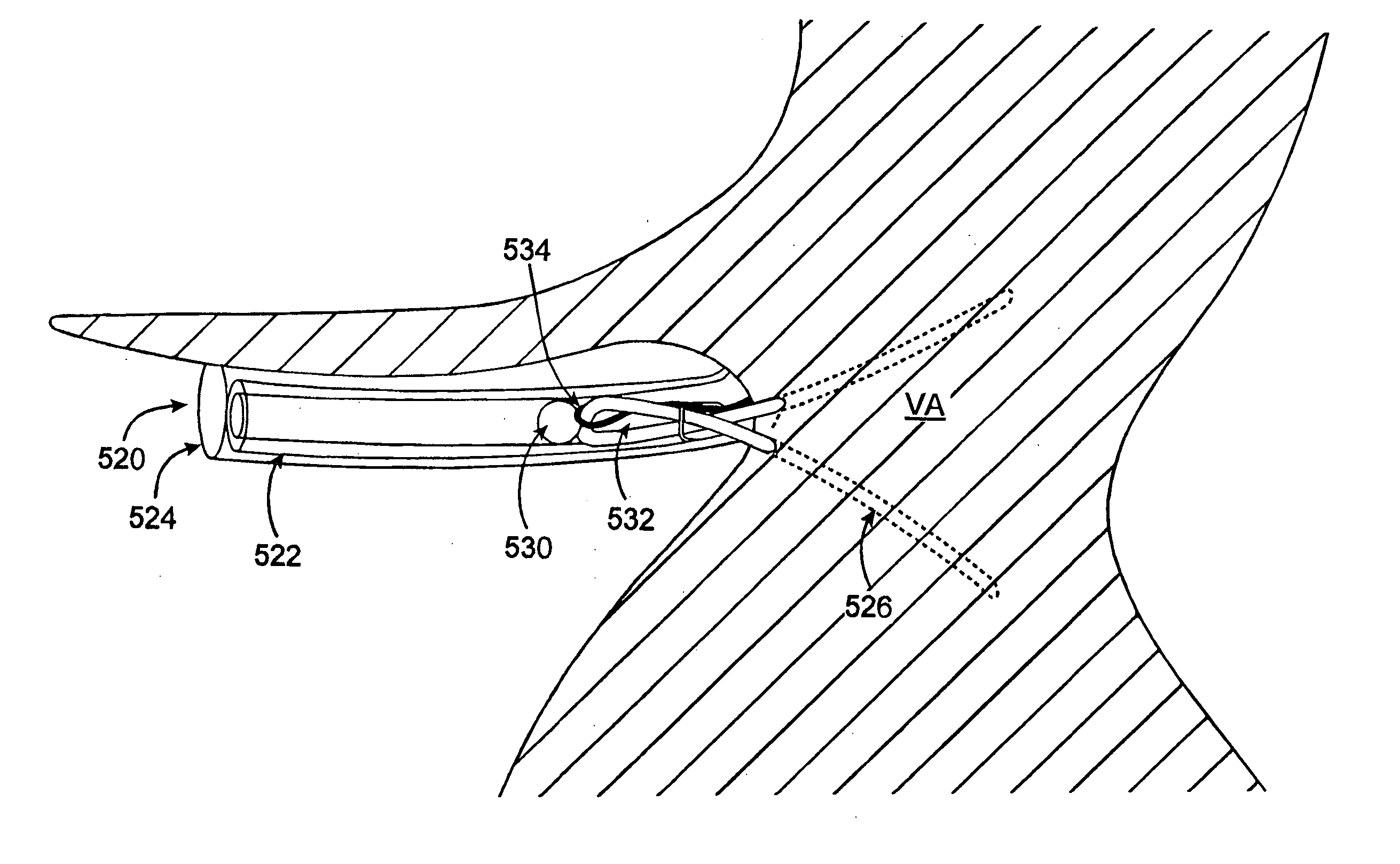
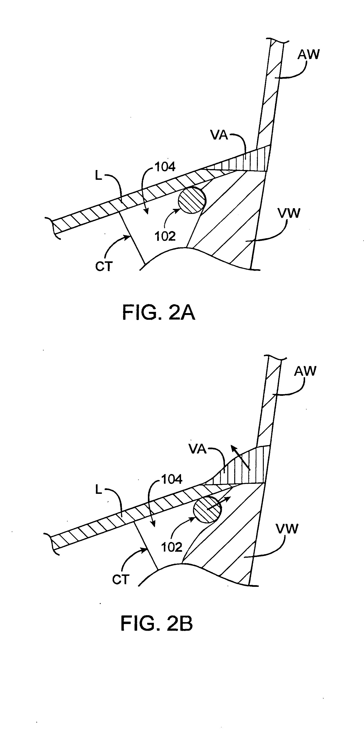
[0021] In one embodiment, the advancing step is carried out using an operational device comprising: a series of the anchors, the anchors comprising a distal anchor and a proximal anchor; and a tether serially coupling the anchors to one another with the proximal anchor coupled to the tether and the distal anchor secured to the tether; and the acting on step comprises: securing the series of anchors to the mitral valve annulus; and pulling on the tether to reduce the distance between the proximal and distal anchors. The method may optionally further comprise selecting an operational device comprising a housing having a diametrical dimension d and an anchor having a diametrical dimension D in the deployed state, and wherein the ratio of D to d is at least 3.5. In one embodiment, the method includes selecting an operational device comprising a housing having a diametrical dimension d and an anchor having a diametrical dimension D in the deployed state, and wherein the ratio of D to d is at least 4.4.
[0024] In another aspect of the present invention, a method for advancing an operational device into a left ventricle of a heart to contact and circumferentially tighten the mitral valve annulus comprising: selecting an operational device comprising an elongate housing having a diametrical dimension d and anchors having a diametrical dimension D in a deployed state, and wherein the ratio of D to d is at least 3.5; advancing the operational device through an aorta and into a left ventricle and along at least a portion of a mitral valve annulus of a heart of a patient, the advancing step being carried out using an operational device comprising: an elongate housing having a longitudinal axis and an open interior; a series of self-forming tissue-engageable anchors, the anchors comprising a distal anchor and a proximal anchor within the open interior of the housing; the anchor having a first part and at least two second parts extending from the first part, the second parts each having a tissue-piercing tip, the second parts having generally circular or semicircular shapes when in the deployed state; a tether serially coupling the anchors to one another with the proximal anchor coupled to the tether and the distal anchor secured to the tether; the housing having openings sized for passage of the anchors tip-first through the opening; and each of the anchors placeable in a relatively straight, undeployed state generally parallel to the longitudinal axis within the housing; urging the operational device radially outwardly to seat the operational device against the mitral valve annulus; securing the series of anchors to the mitral valve annulus by: driving the anchors tip-first through the openings with the anchors naturally assuming curved, tissue-engaging deployed states after passing through the openings in the housing, the anchors oriented generally perpendicular to the longitudinal axis when in the deployed state; and pulling on the tether to reduce the circumferential distance between the proximal and distal anchors and circumferentially tighten the mitral valve annulus.

Problems solved by technology

As mentioned above, difficulties in performing minimally invasive intracardiac surgery include positioning a minimally invasive treatment device in a desired location for performing a procedure and effectively deploying a given treatment into or on the target cardiac tissue.
Positioning an anchor deliver device in a desired location adjacent the annular tissue may often be challenging, especially in an intravascular procedure when visualization of the location is limited.

Method used


Image

  • Delivery devices and methods for heart valve repair
  • Delivery devices and methods for heart valve repair
  • Delivery devices and methods for heart valve repair

Examples


Embodiment Construction

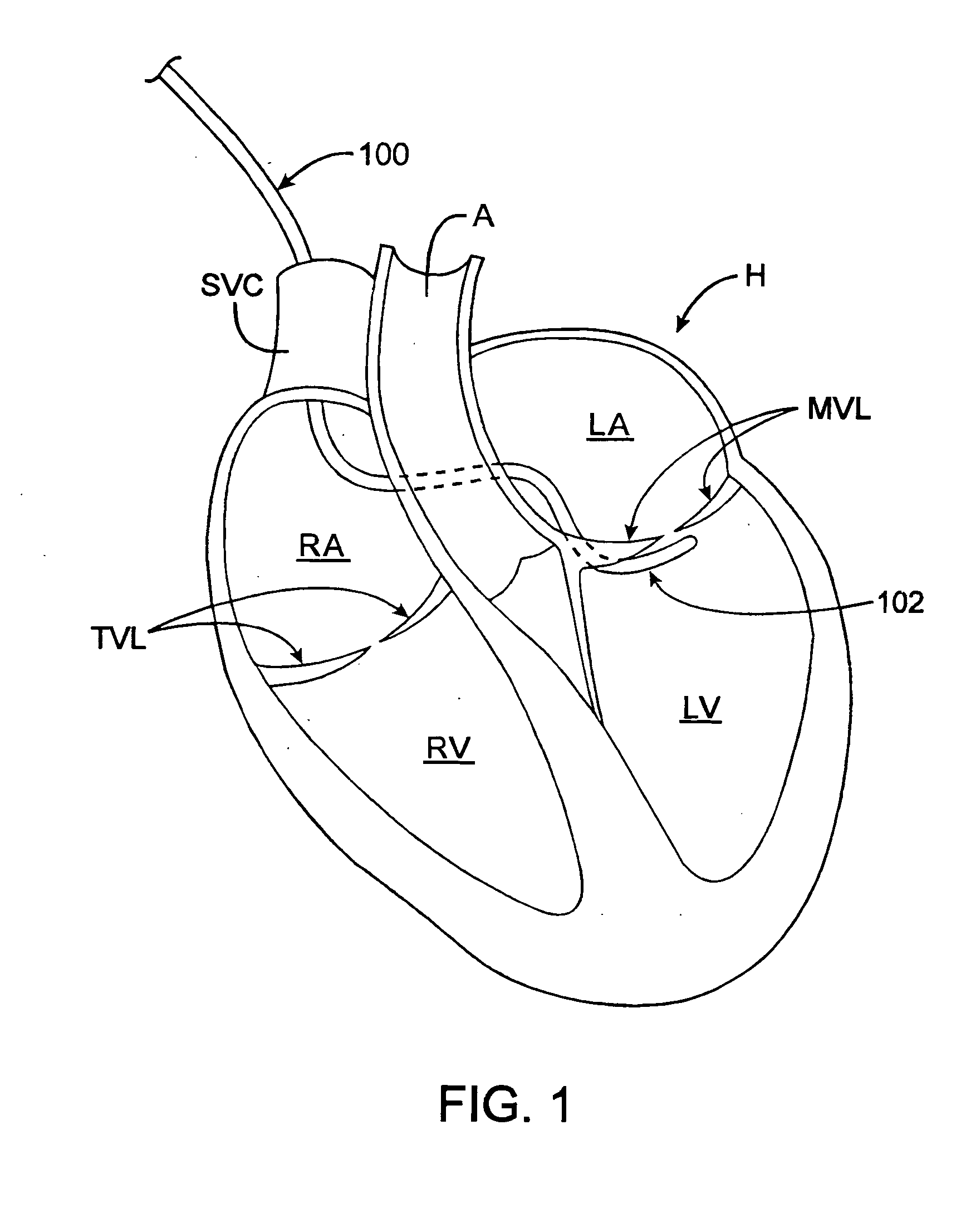
[0041] Devices, systems and methods of the present invention are generally used to facilitate transvascular, minimally invasive and other “less invasivesurgical procedures, by facilitating the delivery of treatment devices at a treatment site. Although the following description focuses on use of devices and methods of the invention for mitral valve repair, the devices and methods may be used in any suitable procedure, both cardiac and non-cardiac. When used for treatment of a cardiac valve annulus, the inventive methods generally involve contacting an anchor delivery device with a length of the valve annulus, delivering a plurality of coupled anchors from the anchor delivery device, and drawing the anchors together to tighten the annulus. Devices include an elongate catheter having a housing at or near the distal end for releasably housing a plurality of coupled anchors, as well as delivery devices for facilitating advancement and / or positioning of an anchor delivery device. Devic...


PUM


Abstract

Devices, systems and methods facilitate positioning of a cardiac valve annulus treatment device, thus enhancing treatment of the annulus. Methods generally involve advancing an anchor delivery device through vasculature of the patient to a location in the heart for treating the valve annulus, contacting the anchor delivery device with a length of the valve annulus, delivering a plurality of coupled anchors from the anchor delivery device to secure the anchors to the annulus, and drawing the anchors together to circumferentially tighten the valve annulus. Devices generally include an elongate catheter having at least one tensioning member and at least one tensioning actuator for deforming a distal portion of the catheter to help it conform to a valve annulus. The catheter device may be used to navigate a subannular space below a mitral valve to facilitate positioning of an anchor delivery device.

Description

CROSS REFERENCE TO RELATED APPLICATIONS [0001] The present application is a continuation of U.S. patent application Ser. No. 10 / 792,681 (Attorney Docket No. 016886-001330US), filed on Mar. 2, 2004, which is a continuation-in-part of U.S. patent application Ser. No. 10 / 741,130 (Attorney Docket No. 016886-001320US), filed on Dec. 19, 2003, which is a continuation-in-part of U.S. patent application Ser. Nos. 10 / 656,797 (Attorney Docket No. 16886-001300US), filed on Sep. 4, 2003, and Ser. No. 10 / 461,043 (Attorney Docket No. 16886-000310US), filed on Jun. 13, 2003, the latter of which claims the benefit of U.S. Provisional Patent Application Nos. 60 / 388,935 (Attorney Docket No. 016886-000300US), filed on Jun. 13, 2002; No. 60 / 429,288 (Attorney Docket No. 016886-000700US), filed on Nov. 25, 2002; and No. 60 / 445,890 (Attorney Docket No. 016886-000800US), filed on Feb. 6, 2003. The full disclosures of all of the above-listed references are herby incorporated by reference. [0002] The present...

Claims


Application Information

Patent Timeline
Patent Type & Authority Applications(United States)
IPC IPC(8): A61B17/00A61B17/04A61B17/064A61B17/068A61B17/08A61F2/24
CPCA61B17/00234A61F2/2466A61B17/064A61B17/068A61B17/0682A61B17/072A61B2017/00243A61B2017/00783A61B2017/00867A61B2017/0409A61B2017/0414A61B2017/0437A61B2017/0464A61B2017/07221A61F2/2445A61B17/0401
Inventor STARKSEN, NIEL F.TO, JOHNMORALES, RODOLFO A.
Owner ANCORA HEART INC
Learn More