Method and apparatus for vacuum stripping of oils and fats

Inactive Publication Date: 2005-03-31
DE SMET ENG
View PDF45 Cites 21 Cited by
  • Summary
  • Abstract
  • Description
  • Claims
  • Application Information

AI Technical Summary

Benefits of technology

[0021] Yet another advantage of the present invention is that by using a single pump to collect the gaseous stripping medium from above each tray in the at least one further downstream stripping vessel, the pressure above these trays can be set to a uniform and sufficiently low value to strip thermal breakdown products.
[0022] The present invention also concerns an apparatus that can be used in the vacuum stripping process of liquid materials such as edible oils, for instance vegetable oil or animal fat, such as described here-above, which apparatus comprises a first stripping vessel; at least one second stripping vessel further downstream from said first stripping vessel, said at least one second stripping vessel containing at least two trays each provided with sparging means (e.g. spargers), the apparatus further comprising a collector connecting said first stripping vessel and said at least one second stripping vessel, said collector being provided with inlet openings above each said tray, which collector is connected to a pump with a discharge into said first stripping vessel.
[0023] In order to better explain the characteristics of the invention, some preferred embodiments of an apparatus that can be used for a vacuum stripping process accor

Problems solved by technology

However, most non-deodorised vegetable oils and animal fats exhibit an excessively strong and unpleasant flavour and therefore must be deodorised.
However, it was soon realised that reducing the pressure below atmospheric diminished the amount of water that had to be distilled to achieve the required extent of deodorization.
This led to deodorization by steam stripping under greatly reduced pressure.
These bubble caps have the disadvantage of constituting a resistance to the gas flow that has to overcome the hydro-static oil height in the tray.
With the oil flowing down by gravity from each tray to the tray below, this means that the oil on the lowest tray is exposed to the highest deodorization pressure and thus to the least effective deodorization conditions.
A disadvantage of the process according to FR 2.103.267 is the re-dissolution of the volatile components into the oil to be deodorised.
By adding the motive steam of the steam ejector to the gas stream, the increase in the volatile content will be somewhat smaller but nevertheless, it is likely that, if the compressed gas stream were to be allowed to reach eq

Method used


Image

  • Method and apparatus for vacuum stripping of oils and fats
  • Method and apparatus for vacuum stripping of oils and fats

Examples


example 2

[0057] If now the second stripping vessel 3 is equipped with two trays 12 and 13 in accordance with the invention, the situation will be quite different from that of example 1. The volatile concentration in the vapour before compression would be only (0.5+0.25)V / (2*S+(0.5+0.25)V) or, after simplification 0.75*V / (2*S) 0.38*V / S, which is lower than the value of 0.5*V / S calculated for the single tray situation. After compression this concentration would increase to 2*0.38V / (1.4*S) or 0.54 V / S. This means that the compressed vapour stream will not be supersaturated with respect to the oil leaving the first stripping vessel 2 and consequently, no volatile components will dissolve in the oil being stripped in this vessel 2. On the contrary, the vapour stream can still accommodate some volatile compounds at the pressure pertaining at the bottom end of said first stripping vessel 2 and will strip out more volatile compounds when it rises to areas of lower pressure and is brought into contac...

example 3

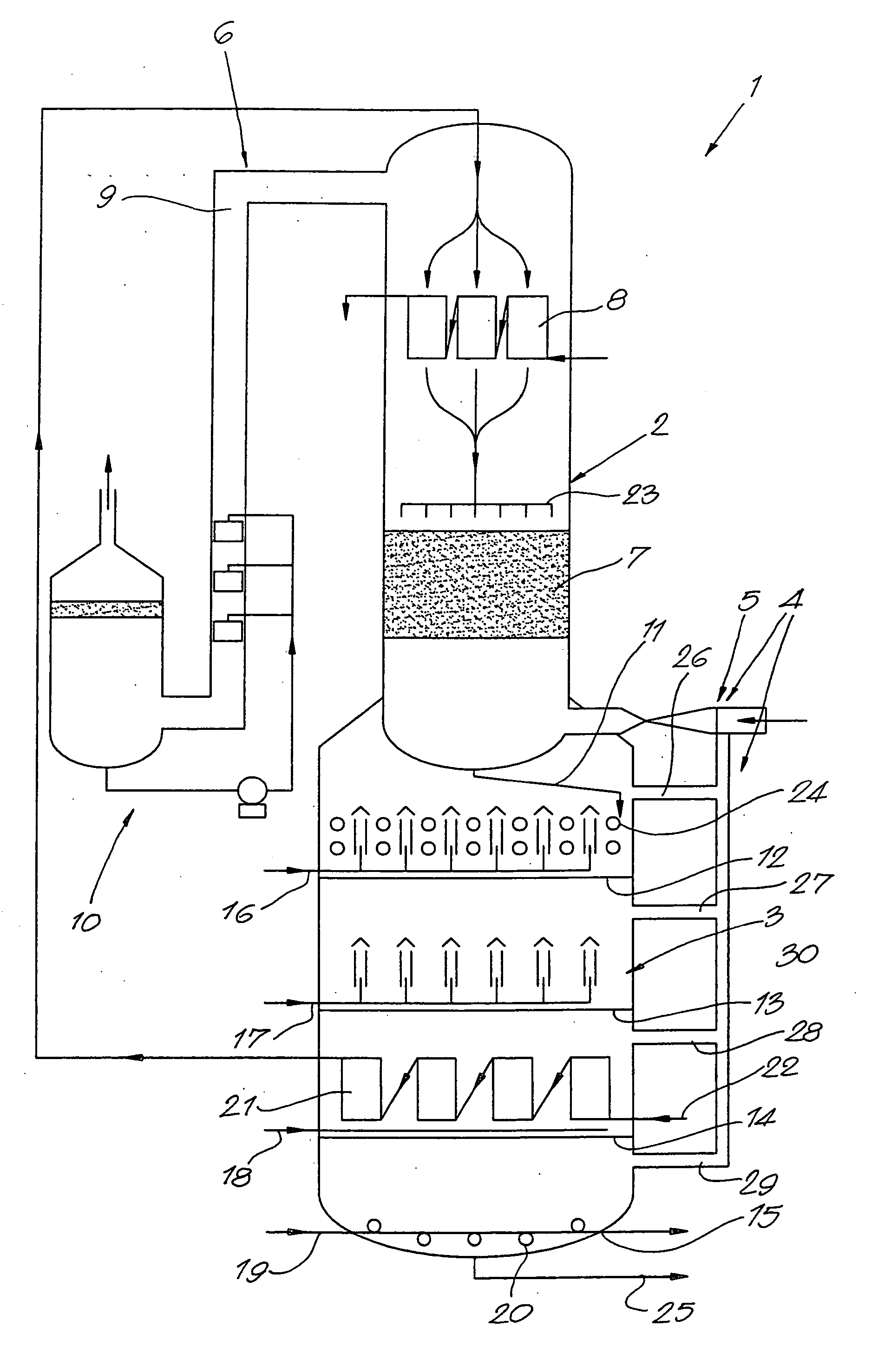
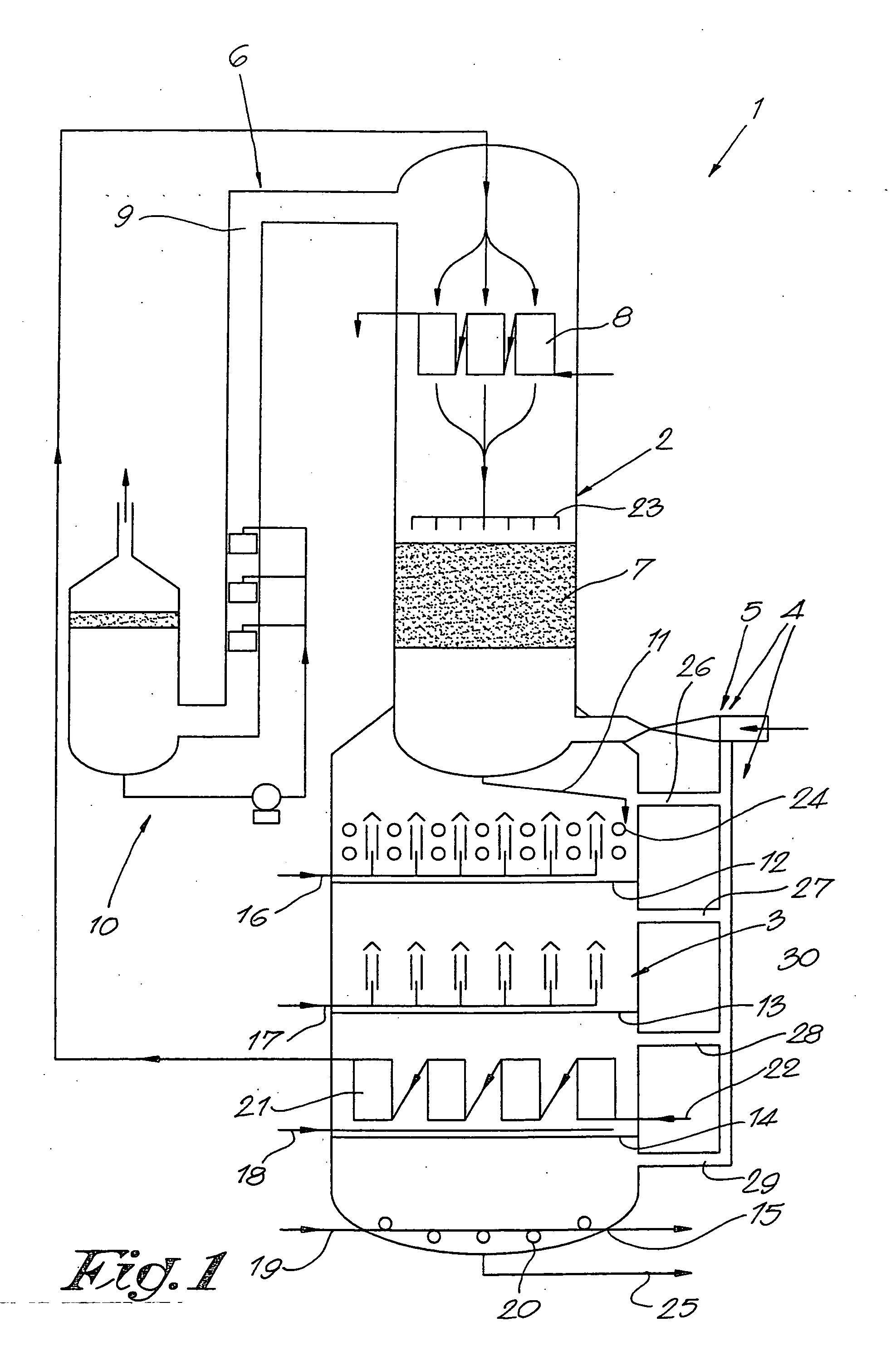
[0059] In order to illustrate the apparatus that can be profitably used in the process according to the invention, reference is again made to FIG. 1, giving a cross section of a deodoriser apparatus for performing the invention. This deodoriser comprises or consists of a shell, having an upper first stripping vessel 2 and a lower second stripping vessel 3.

[0060] De-gummed and bleached oil with a free fatty acid content of 5% by weight, calculated on the basis of oleic acid, is supplied to the deodoriser by a pump (not shown) via a heat exchanger 21 located in the second stripping vessel 3, where the incoming oil is pre-heated by the outgoing oil and via a further heater 8 located in the first stripping vessel 2, where the pre-heated oil is brought to process temperature by indirect heating with high pressure steam.

[0061] From the heater 8, the oil flows down through the packing 7 located in the first stripping vessel 2, whereby a distributor 23 ensures, an even distribution of the...


PUM


Abstract

An apparatus for use in a vacuum stripping process comprises a first stripping vessel (2); at least one second further downstream stripping vessel (3), said at least one second further downstream stripping vessel (3) containing at least two trays (12), (13), (14) and (15) each provided with sparging means (16), (17), (18) and (19) respectively, and further comprises a collector (4) connecting said first stripping vessel (2) and said at least one second stripping vessel (3), said collector (4) being provided with inlet openings above each said tray (12), (13), (14) and (15) and said collector (4) being connected to a pump (5) with a discharge into said first stripping vessel (2).

Description

[0001] The present invention concerns a method for vacuum stripping, especially a method for vacuum stripping as used in the physical refining and deodorization of fatty glycerides, herein-after referred as edible oils, such as but not limited to vegetable oils, hydrogenated vegetable oils and animal fats as well as an apparatus for vacuum stripping of such materials. [0002] Vegetable oils as produced by expelling and / or solvent extraction of oil seeds and animal fats as produced by rendering, often require deodorization to obtain a bland tasting final product. Only a few oils, as for instance virgin olive oil, are not subjected to such a deodorization treatment. Such non-deodorised oils thus retain their particular flavour for which some customers appreciate them. However, most non-deodorised vegetable oils and animal fats exhibit an excessively strong and unpleasant flavour and therefore must be deodorised. [0003] The earliest deodorization processes involved mixing a vegetable oi...

Claims


Application Information

Patent Timeline
IPC IPC(8): B01D3/34B01D3/38C11B3/12C11B3/14
CPCB01D3/346C11B3/14C11B3/12B01D3/38
Inventor KELLENS, MARCDE SURAY, DIMITRI
Owner DE SMET ENG
Why Eureka
Try Eureka