Method of producing multi-terminal type laminated ceramic electronic component

a laminated ceramic electronic component and multi-terminal technology, applied in the direction of fixed capacitor details, stacked capacitors, fixed capacitors, etc., can solve the problems of unsatisfactory spread and difficulty in producing laminated ceramic electronic components having desired internal electrode patterns printed with high accuracy, and achieve high accuracy and effective enhancement of printing accuracy of internal electrode patterns

Active Publication Date: 2005-03-31
MURATA MFG CO LTD
View PDF18 Cites 29 Cited by
  • Summary
  • Abstract
  • Description
  • Claims
  • Application Information

AI Technical Summary

Benefits of technology

[0015] In order to overcome the problems described above, preferred embodiments of the present invention provide a method of producing a multi-terminal type laminated ceramic electronic component provided with a plurality of internal electrodes each having plural lead-out electrodes, the internal electrodes being laminated to each other via ceramic layers, in which in the formation of a mother laminate, the printing accuracy of an internal electrode pattern can be effectively enhanced, and thereby, desired internal electrodes can be formed with high accuracy.

Problems solved by technology

However, the following problem occurs.
Thus, in the case in which portions surrounded by the internal electrode pattern and not coated with the internal electrode conductive paste exist, the applied conductive paste can not be further extended, and thus, tends to undesirably spread, as shown by the arrow A.
Thus, it has been difficult to produce a laminated ceramic electronic component having desired internal electrodes printed with high accuracy.

Method used


Image

  • Method of producing multi-terminal type laminated ceramic electronic component
  • Method of producing multi-terminal type laminated ceramic electronic component
  • Method of producing multi-terminal type laminated ceramic electronic component

Examples


first preferred embodiment

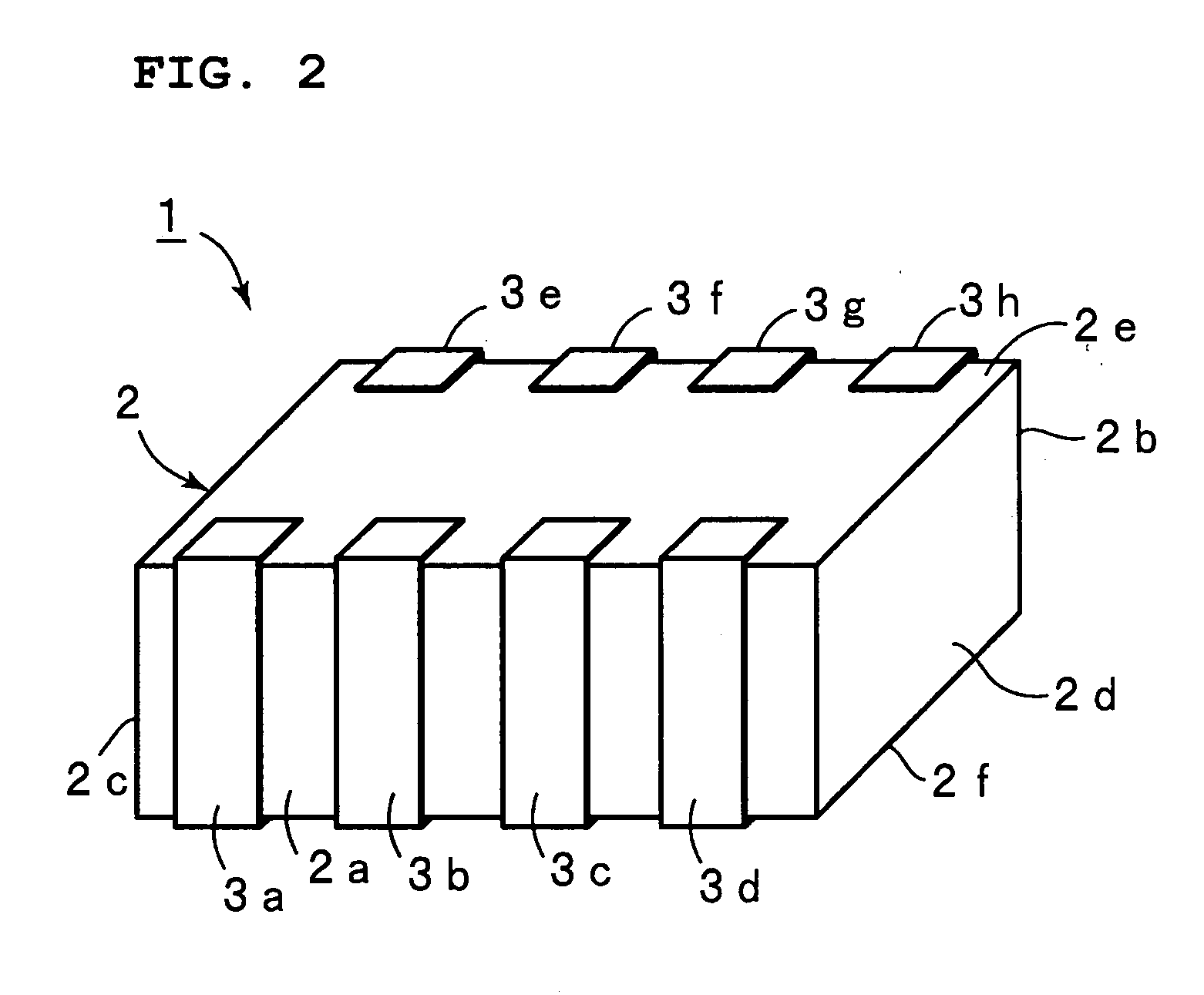
[0047]FIG. 2 is a perspective view of a multi-terminal type monolithic ceramic capacitor as a multi-terminal type laminated ceramic electronic component produced according to a first preferred embodiment of the present invention. The multi-terminal monolithic ceramic capacitor 1 includes a sintered member 2. The shape of the sintered member 2 is preferably substantially rectangular and has a first side surface 2a and a second side surface 2b opposed to each other, side surfaces 2c and 2d, an upper surface 2e and a lower surface 2f.

[0048] First terminal electrodes 3a to 3d are formed on the first surface 2a. Second terminal electrodes 3e to 3h are formed on the second side surface 2b. The terminal electrodes 3a to 3d formed on the first side surface 3a are opposed to the terminal electrodes 3e to 3h formed on the second side surface 2b via the sintered member 2.

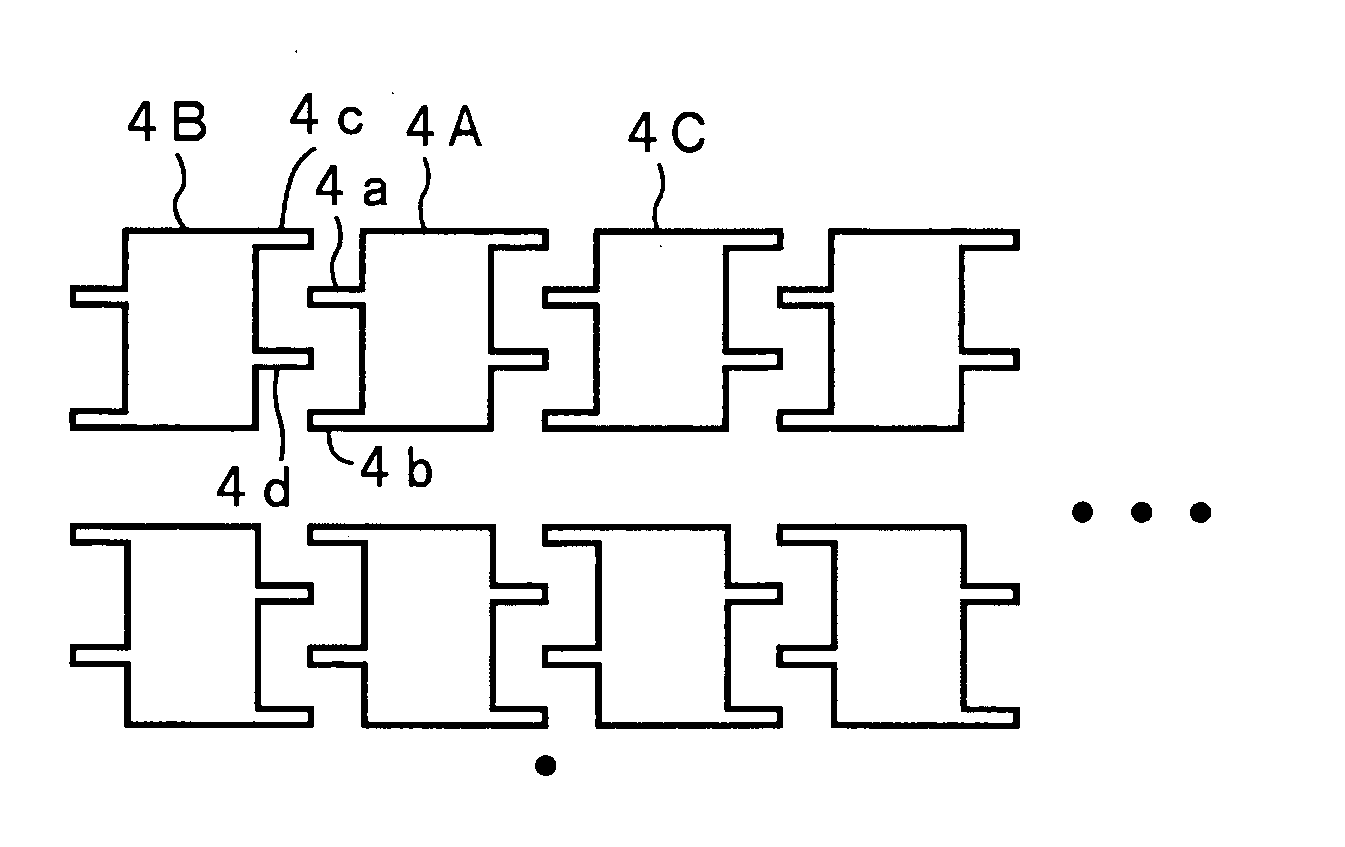
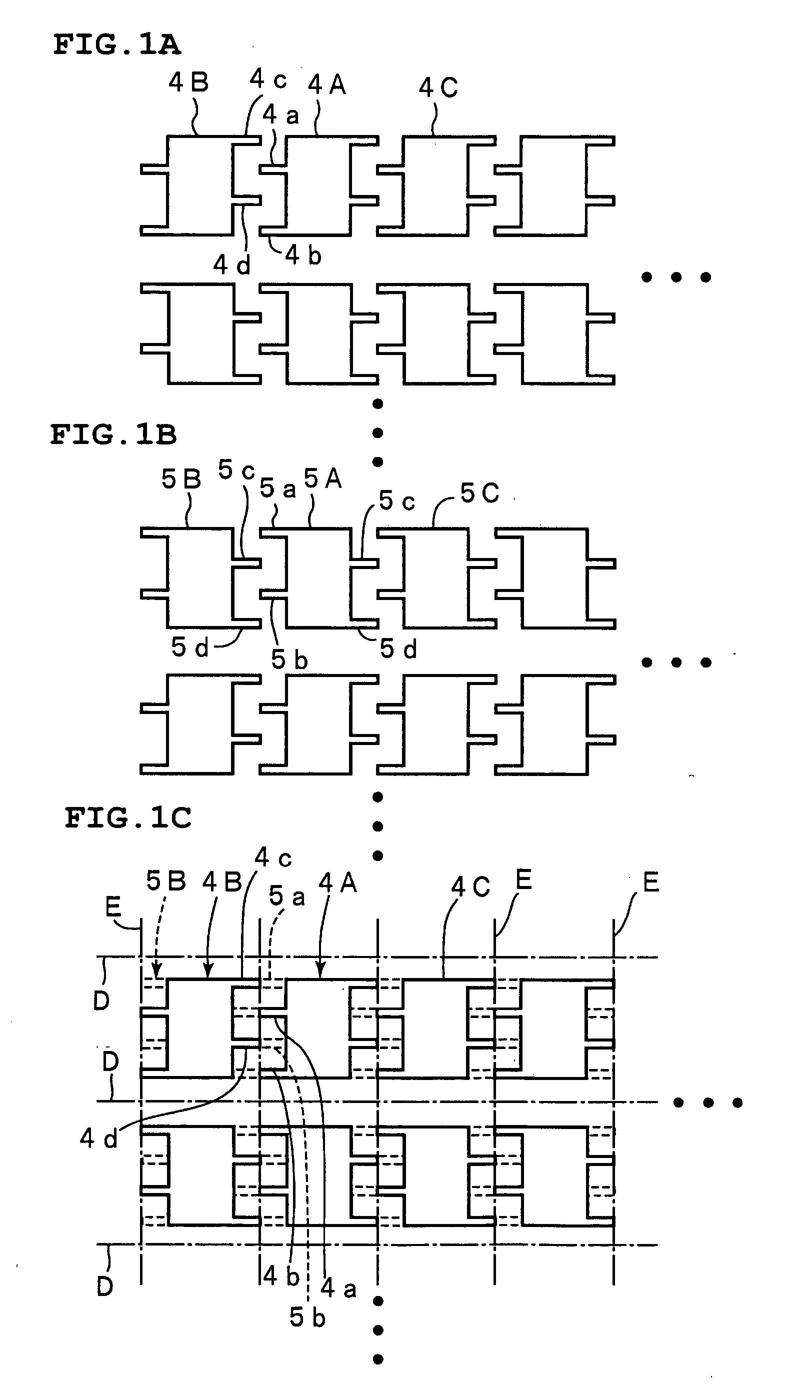
[0049] A plurality of internal electrodes are formed inside of the sintered member 2. FIGS. 3A and 3B are schematic views ...

second preferred embodiment

[0069]FIGS. 7A and 7B are schematic plan views showing internal electrode patterns which are formed according to the production method of a second preferred embodiment of the present invention. FIG. 8 is a perspective view of a multi-terminal type monolithic ceramic capacitor which is produced according to the second preferred embodiment of the present invention.

[0070] In the multi-terminal monolithic ceramic capacitor 11, third terminal electrodes 12a and 12b are formed on a side surface 2c of the sintered member 2, and fourth terminal electrodes 12c and 12d are formed on a side surface 2d thereof, as shown in FIG. 8.

[0071] Moreover, first terminal electrodes 12e to 12i are formed on the side surface 2a of the sintered member 2, and second terminal electrodes 12j to 12n are formed on the side surface 2b thereof.

[0072] Thus, a lager number of the terminal electrodes 12e to 12j are formed on the side surface 2a, and a larger number of the terminal electrodes 12j to 12n are formed ...

third preferred embodiment

[0076]FIGS. 9A to 9C illustrate a method of producing a multi-terminal type monolithic ceramic capacitor according to a third preferred embodiment of the present invention. FIGS. 9A and 9B are plan views showing internal electrode patterns to be laminated onto the each other. FIG. 9C is a schematic plan view showing the lamination of the internal electrode patterns in the mother laminate. FIGS. 9A to 9C correspond to FIGS. 1A to 1C in the first preferred embodiment of the present invention.

[0077] One of the unique features of the third preferred embodiment lies in that the lead-out electrodes of the lengths of internal electrodes adjacent to each other are different from those of the lead-out electrodes in the first preferred embodiment of the present invention. This will be described with respect to the internal electrodes 4A and the internal electrodes 4B shown in FIG. 9A as examples. The tips of the lead-out electrodes 4a and 4b of the internal electrode 4A and the tips of the l...


PUM

PropertyMeasurementUnit
thicknessaaaaaaaaaa
conductiveaaaaaaaaaa
electric currentsaaaaaaaaaa

Abstract

In a method of producing a multi-terminal type laminated ceramic electronic component in which internal electrodes are embedded in a sintered ceramic member, and the internal electrodes have plural first lead-out electrodes led out to a first side surface and plural second lead-out electrodes led out to a second side surface, the plural second lead-out electrodes of one of the adjacent internal electrodes in each internal electrode pattern are not continuous with the plural first lead-out electrodes of the other of the adjacent internal electrodes, and the plural second lead-out electrodes and the plural first lead-out electrodes are alternately arranged in a direction that is substantially perpendicular to the direction of a line connecting the first and second side surfaces.

Description

BACKGROUND OF THE INVENTION [0001] 1. Field of the Invention [0002] The present invention relates to a method of producing a multi-terminal type laminated ceramic electronic component such as a multi-terminal monolithic ceramic capacitor or other suitable device, and in particular, to a method of producing a multi-terminal type laminated ceramic electronic component, the method using an internal electrode pattern in which the shapes of lead-out electrodes which are continuous with an internal electrode are significantly improved. [0003] 2. Description of the Related Art [0004] Previously, a variety of multi-terminal type laminated ceramic electronic components have been proposed in which a plurality of internal electrodes connected to plural terminal electrodes are laminated to each other via ceramic layers. For example, in Japanese Unexamined Patent Application Publication No. 2-256216, FIG. 16 schematically shows a multi-terminal type monolithic ceramic capacitor 101. As shown in ...

Claims


Application Information

Patent Timeline
Patent Type & Authority Applications(United States)
IPC IPC(8): B32B18/00H01G4/38H01G4/12H01G4/232H01G4/30
CPCB32B18/00H01G4/232C04B2237/68C04B2237/32H01G4/30H01G4/12
Inventor ITO, TSUYOSHITANIGUCHI, MASAAKI
Owner MURATA MFG CO LTD
Why Eureka
Try Eureka