Device for welding of a foil tube

a technology for foil tubes and devices, applied in the direction of lamination, lamination, external supports, etc., can solve problems such as space problems, and achieve the effects of precise pressure adjustment, high sealing pressure, and quick and location-controlled jaw movements

Inactive Publication Date: 2005-03-31
ROVEMA VERPACKUNGSMASCHEN
View PDF7 Cites 2 Cited by
  • Summary
  • Abstract
  • Description
  • Claims
  • Application Information

AI Technical Summary

Benefits of technology

[0015] When, according to claim 7, the linear drive is designed as a linear motor, which operates according to the principle of a suspension railway, then very quick and location-precise controllable jaw movements can be achieved. This electromagnetic linear drive has, in addition, the advantage that a relatively high sealing pressure of ap

Problems solved by technology

The known device has the disadvantage that it has a rod, which serves as a lever to enlarge the welding pressure.
This rod reaches downwardly to the linear drive and

Method used


Image

  • Device for welding of a foil tube
  • Device for welding of a foil tube
  • Device for welding of a foil tube

Examples


Embodiment Construction

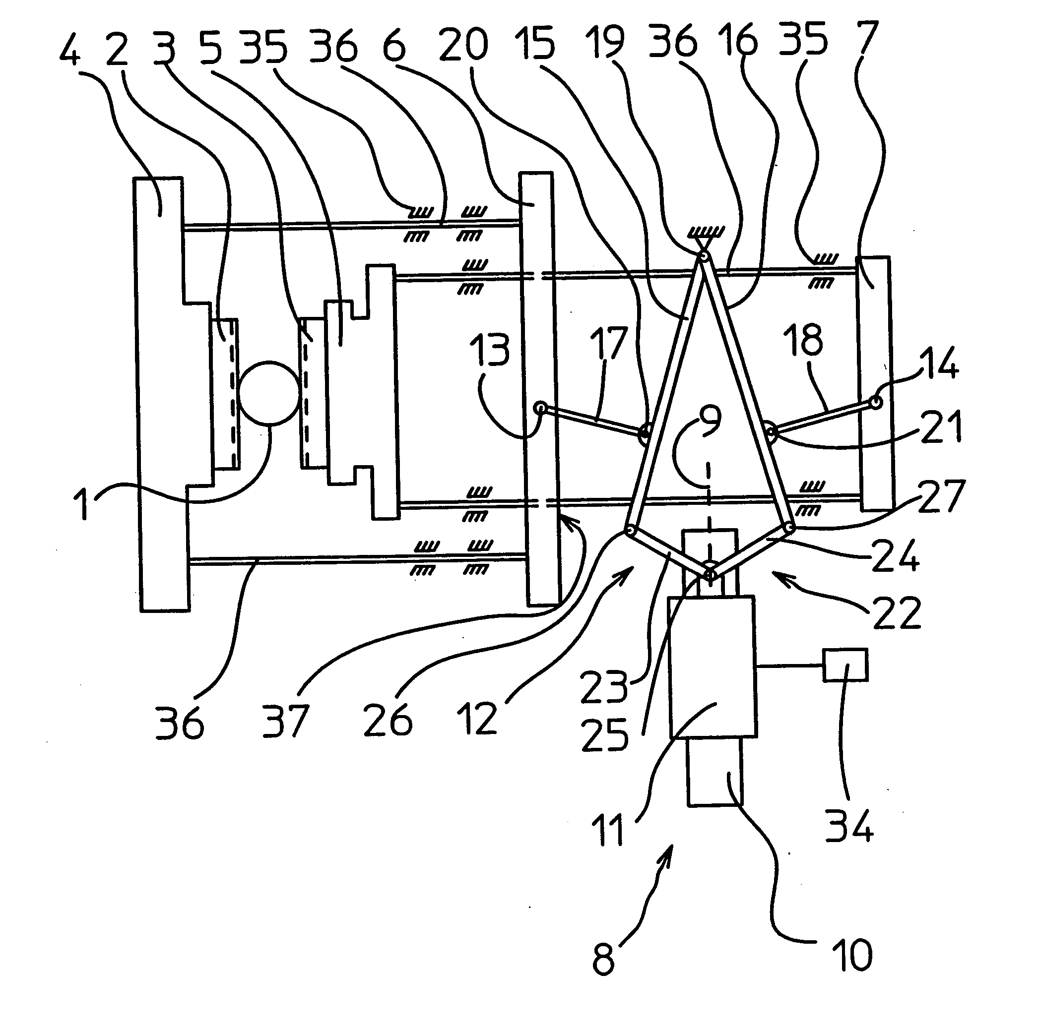
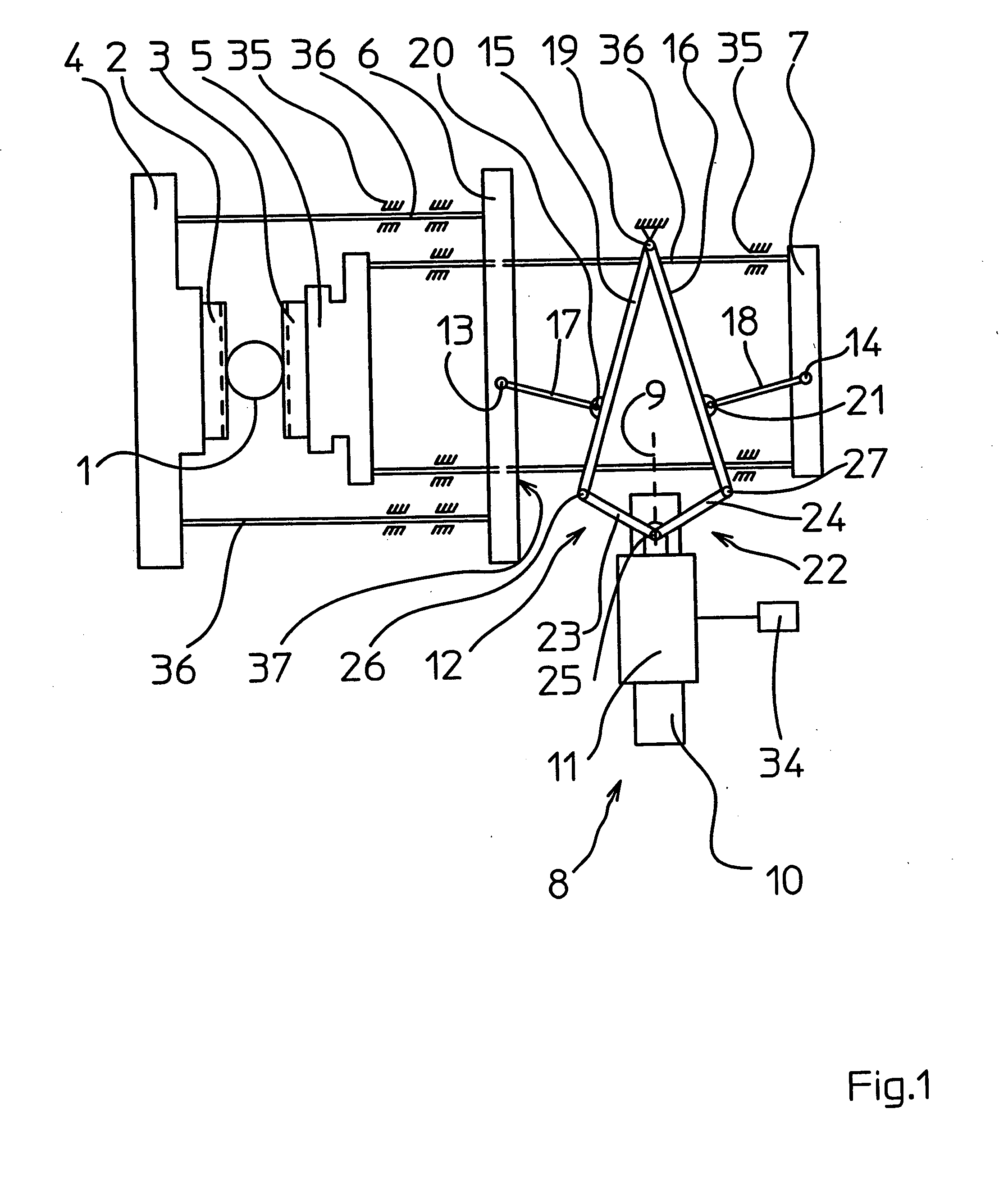
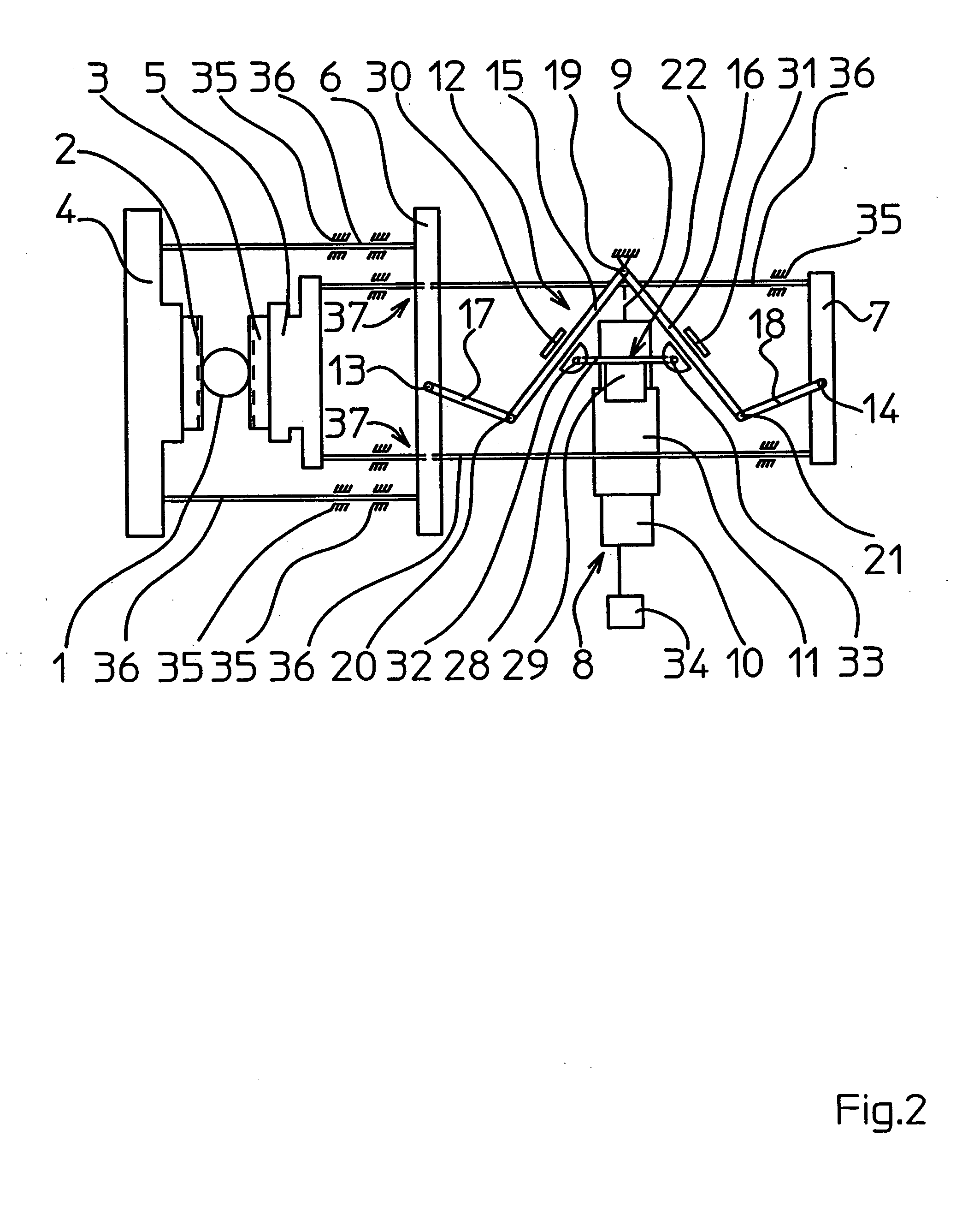
[0020] In a device for welding of a foil tube 1, this welding occurs by means of two welding jaws 2, 3, which can be moved against one another and clamp the foil tube 1 between one another (FIG. 1). Two jaw holders 4, 5 are used to hold each one welding jaw 2, 3 and jaw carriers 6, 7 are each used to carry one jaw holder 4, 5 and thus the welding jaws 2, 3. The jaw carriers 6, 7 are each connected to the jaw holders 4, 5 by two rigid connections 36 guided in guideways 35. Two connections 36 are further inserted in a sliding manner through two openings 37 of the jaw carrier 6. A linear drive 8 with a part 11, which is linearly movable along an active line 9 and a stationary part 10, serves as the drive for the jaw movement. The movable part 11 is connected to the gearing 12. Also the gearing 12 is connected to the jaw carriers 6, 7 in order to create an opposing movement of the jaw carriers 6, 7 and thus of the welding jaws 2, 3 in order to be able to move the welding jaws 2, 3 towar...


PUM

PropertyMeasurementUnit
Timeaaaaaaaaaa

Abstract

In order to achieve, in a device for welding of a foil tube comprising two welding jaws, which can be moved against one another and clamp the foil tube between one another, a relatively low building height of the device and a high welding force, it is suggested that a gearing has four rods, of which two inner rods are pivotally fastened through a stationary joint, and two outer rods are each connected through one joint to an inner rod and a further joint to a jaw carrier, and that a movable part of a linear drive is connected to the inner rods through a connecting member in order to pivot the inner rods and thus the jaw carriers away from one another or toward one another during a movement of the movable part along its active line.

Description

FIELD OF THE INVENTION [0001] The subject matter of the patent application is a device for welding of a foil tube for packaging purposes. BACKGROUND OF THE INVENTION [0002] Vertical tubular bagging machines are known, with which top-side and bottom-side welded, filled tubular bags are manufactured. A foil tube is for this purpose initially longitudinally welded. Then the foil tube is filled, is welded transversely to its transport direction, and a finished tubular bag is separated from the foil tube. [0003] Many different drives and gearings are known to operate the welding jaws, which carry out the cross-welding of the foil tube in order to produce the top and bottom seams of the tubular bags. [0004] A device according to the generic term of claim 1 is known from the DE 196 27 892 A1, which device, is suited for this cross-welding. [0005] The foil tube is in this known device welded by means of two welding jaws, which are movable against one another and clamp the foil tube between ...

Claims


Application Information

Patent Timeline
IPC IPC(8): B29C65/00B65B51/30
CPCB29C65/02Y10T156/1744B29C66/43B29C66/822B29C66/8221B29C66/8226B29C66/8244B29C66/849B65B51/303B29C66/1122Y10T156/17B29C65/00B29C66/4312
Inventor KAMMLER, ROMANBAUR, WALTER
Owner ROVEMA VERPACKUNGSMASCHEN
Why Eureka
Try Eureka