
Stator cooling method and apparatus

a technology for electric motors and cooling methods, applied in the direction of windings, magnetic circuit rotating parts, magnetic circuit shapes/forms/constructions, etc., can solve the problems of system downtime, degrade the performance of the motor, and heat produced by the physical interaction of the various moving parts of the motor, so as to achieve efficient cooling of the motor

Inactive Publication Date: 2005-03-31
RELIANCE ELECTRIC TECH
View PDF7 Cites 44 Cited by
  • Summary
  • Abstract
  • Description
  • Claims
  • Application Information

AI Technical Summary

Benefits of technology

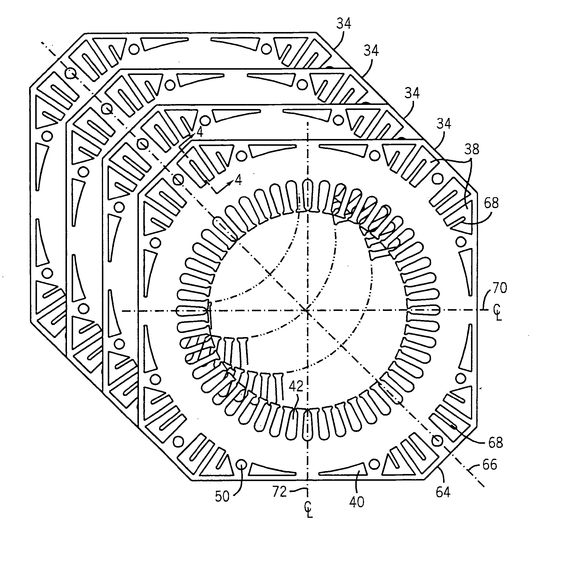
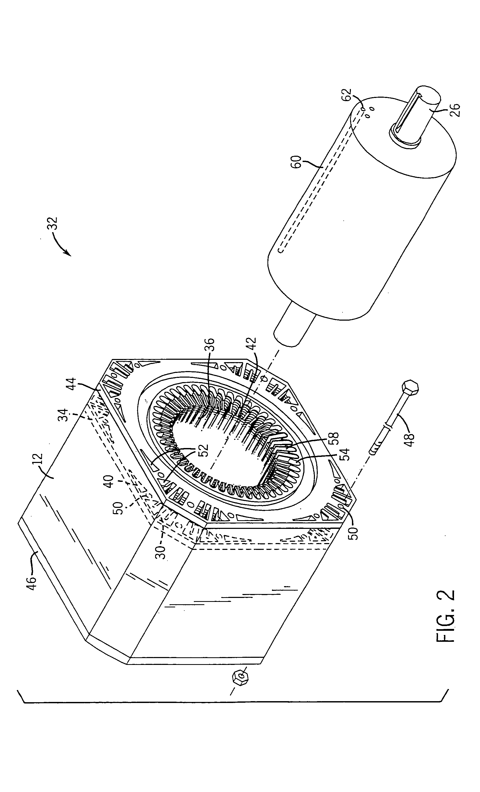
[0007] The present invention provides an improved technique for cooling electric motors. The technique may be applied in a wide range of settings, but is particularly well suited for use in industrial, ac motors having a laminated construction. In one exemplary embodiment of the present technique, a lamination having a plurality of cooling ducts is provided. The lamination presents a generally square cross section having chamfered corners. Disposed in each of these chamfered corners is a corner duct that facilitates convective cooling of the motor during operation. Additionally, the lamination includes center ducts disposed about the vertical and horizontal centerlines of the lamination. When installed into a motor, the center ducts also facilitate convective cooling of the motor during operation thereof.
[0008] According to another embodiment, the present technique provides a lamination having corner ducts located in each of the chamfered corners. Additionally, the exemplary lamination includes at least one fin disposed in each of the corner ducts. Advantageously, the fin improves air flow distribution through the motor and provides additional cooling proprieties. For example, the fins may draw in heat from the air flow, thereby increasing the air flow capacity to draw heat away from the stator.
[0010] According to another exemplary embodiment, the present technique provides a method of cooling a lamination motor. The method comprises providing a forced air flow to the laminate frame motor. The method also comprises routing the forced air flow through corner ducts respectively located in each of the chamfered corners of a lamination and through center ducts located about vertical and horizontal centerlines of the lamination. Advantageously, the exemplary technique distributes the cooling air flow throughout the motor, thereby efficiently cooling the motor.

Problems solved by technology

Indeed, physical interaction of the motor's various moving components may produce heat by way of friction.
If left unabated, excess heat may degrade the performance of the motor.
Worse yet, excess heat may contribute to any number of malfunctions, which may lead to system downtime and require maintenance.
Undeniably, reduced efficiency and malfunctions are undesirable events that may lead to increased costs.
Unfortunately, typical motor designs do not efficiently distribute air flow through the motor.
In other words, little or no air flow results through certain passages, thereby leading to an inefficient distribution and use of the air flow.
Uneven air flow may lead to large variations in operating temperatures at various locations in the motor.
Hotspots generally indicate that cooling resources are not being efficiently employed.
Moreover, localized high operating temperatures (i.e., hotspots), sustained over a relatively long period of time, may lead to premature malfunction of the given location.

Method used


Image

  • Stator cooling method and apparatus
  • Stator cooling method and apparatus
  • Stator cooling method and apparatus

Examples


Embodiment Construction

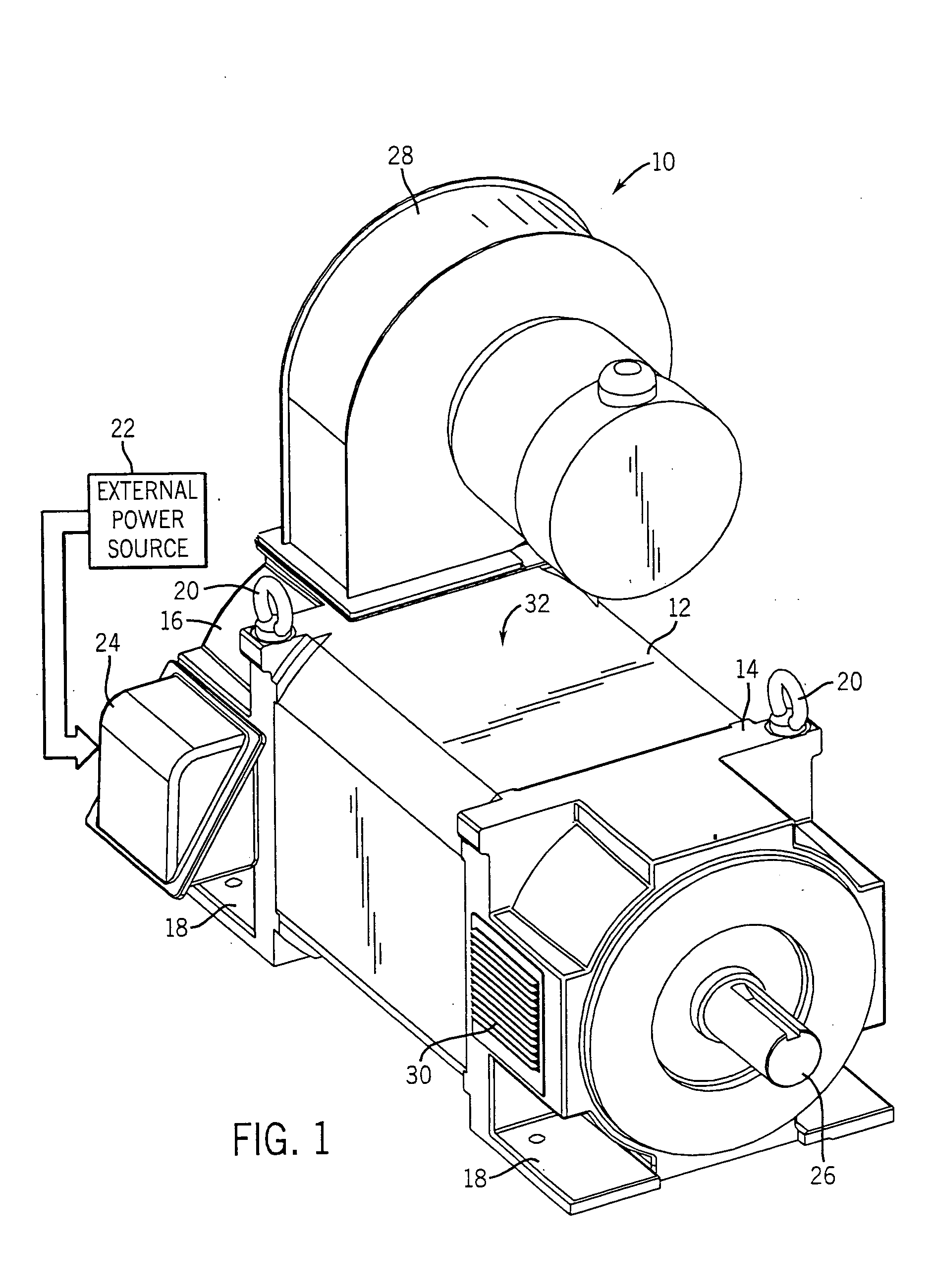
[0017] Turning to the drawings and referring first to FIG. 1, an exemplary electric motor 10 is shown. In the embodiment illustrated, the motor 10 is an induction motor housed in a conventional NEMA enclosure, which is generally employed in industrial settings. Although the present technique is described in relation to an industrial application, it may also be applied to any number of modalities, such as, commercial and residential applications. The motor 10 comprises a frame housing 12 capped at each end by front and rear end-caps 14 and 16, respectively. The frame housing 12 presents a generally square cross section having chamfered corners to conform with the shape of the individual laminations (see FIG. 2) disposed therein. Advantageously, the end-plates 14 and 16 may include mounting and transportation features, such as mounting flanges 18 and eyehooks 20. The frame housing 12 working with the front and rear end-caps 14 and 16, form a protective shell for a stator and a rotor (...


PUM


Abstract

According to one embodiment of the present technique, forced air (i.e., air flow) is routed through a motor stator having corners and center ducts. Advantageously, by routing the air flow through ducts in accordance with the present technique, air flow is more evenly distributed throughout the motor, thereby reducing hotspots. By way of example, the motor stator my include fins that affect air flow and provide heat dissipation surfaces to the motor.

Description

BACKGROUND OF THE INVENTION [0001] The present invention relates generally to the field of electric motors and to methods and apparatus for cooling electric motors. More particularly, the invention relates to a novel technique for dissipating heat in the motor by directing forced air flow through the motor. [0002] Electric motors of various types are commonly found in industrial, commercial and consumer settings. In industry, such motors are employed to drive various kinds of machinery, such as pumps, conveyors, compressors, fans and so forth, to mention only a few. Conventional alternating current electric (ac) motors may be constructed for single or multiple phase power, and are typically designed to operate at predetermined speeds, such as 3600 rpm, 1800 rpm, 1200 rpm, and so on. Such motors generally include a stator, comprising a multiplicity of coils, surrounding a rotor, which is supported by bearings for rotation in the motor frame. In the case of ac motors, ac power applied...

Claims


Application Information

Patent Timeline
IPC IPC(8): H02K1/20
CPCH02K1/20
Inventor MANEY, MARKMARTINEVON, THOMASDONG, QIMIN
Owner RELIANCE ELECTRIC TECH
Learn More