Device and method for increasing the operating range of an electrical circuit

a technology of electrical circuit and operating range, which is applied in the field of circuits, can solve the problems of difficult to achieve tuning voltages that are at or below the maximum supply voltage of advanced (deep sub-micron) cmos technologies, reducing the supply voltage of scaled cmos technologies further complicating this concern, and achieving constant voltage differences. , the effect of constant voltage differen

Inactive Publication Date: 2005-03-31
INTERUNIVERSITAIR MICRO ELECTRONICS CENT (IMEC VZW)
View PDF13 Cites 12 Cited by
  • Summary
  • Abstract
  • Description
  • Claims
  • Application Information

AI Technical Summary

Benefits of technology

Embodiments of the present invention may be employed to generate a tuning voltage (and to supply an associated current) at a voltage higher than a supply voltage (e.g., the supply voltage of a deep sub-micron CMOS technology). In one embodiment, such a circuit (which may be termed a “charge pump circuit”) comprises a first circuit, a second circuit and a high voltage generator. The first circuit, in operation, receives at least one low voltage signal at an input terminal and provides an output voltage signal corresponding to the at least one low voltage signal. The second circuit, in operation, receives a clock signal and the output voltage signal from the first circuit. The second circuit also sends a request signal to the high voltage generator when the output voltage signal does not match reference voltages signals. The high voltage generator, in response to the request signal, sends two supply voltage signals (on which the reference voltage signals are based) to the first circuit and the second circuit. The two supply voltage signals have a substantially constant voltage difference. Further, the high voltage generator, in operation, adjusts the potential of the two supply voltage signals, until the voltage potential of the output voltage signal is between two reference voltage signals that are derived from the supply voltage signals.

Problems solved by technology

Although the required tuning voltage of tunable MEMS devices may be modified by making design changes, it is extremely difficult to achieve a tuning voltage that is at or below the maximum supply voltage of advanced (deep sub-micron) CMOS technologies.
Further, the rapidly decreasing supply voltages of scaled CMOS technologies further complicates this concern.
Moreover, there are design / performance trade offs between the tuning voltage and other parameters of MEMS devices (e.g., mechanical resonance frequency, electrical losses and linearity of the device).
Such dedicated high voltage devices and / or manufacturing process modifications are typically undesirable due to the cost associated with such approaches.

Method used


Image

  • Device and method for increasing the operating range of an electrical circuit
  • Device and method for increasing the operating range of an electrical circuit
  • Device and method for increasing the operating range of an electrical circuit

Examples


Embodiment Construction

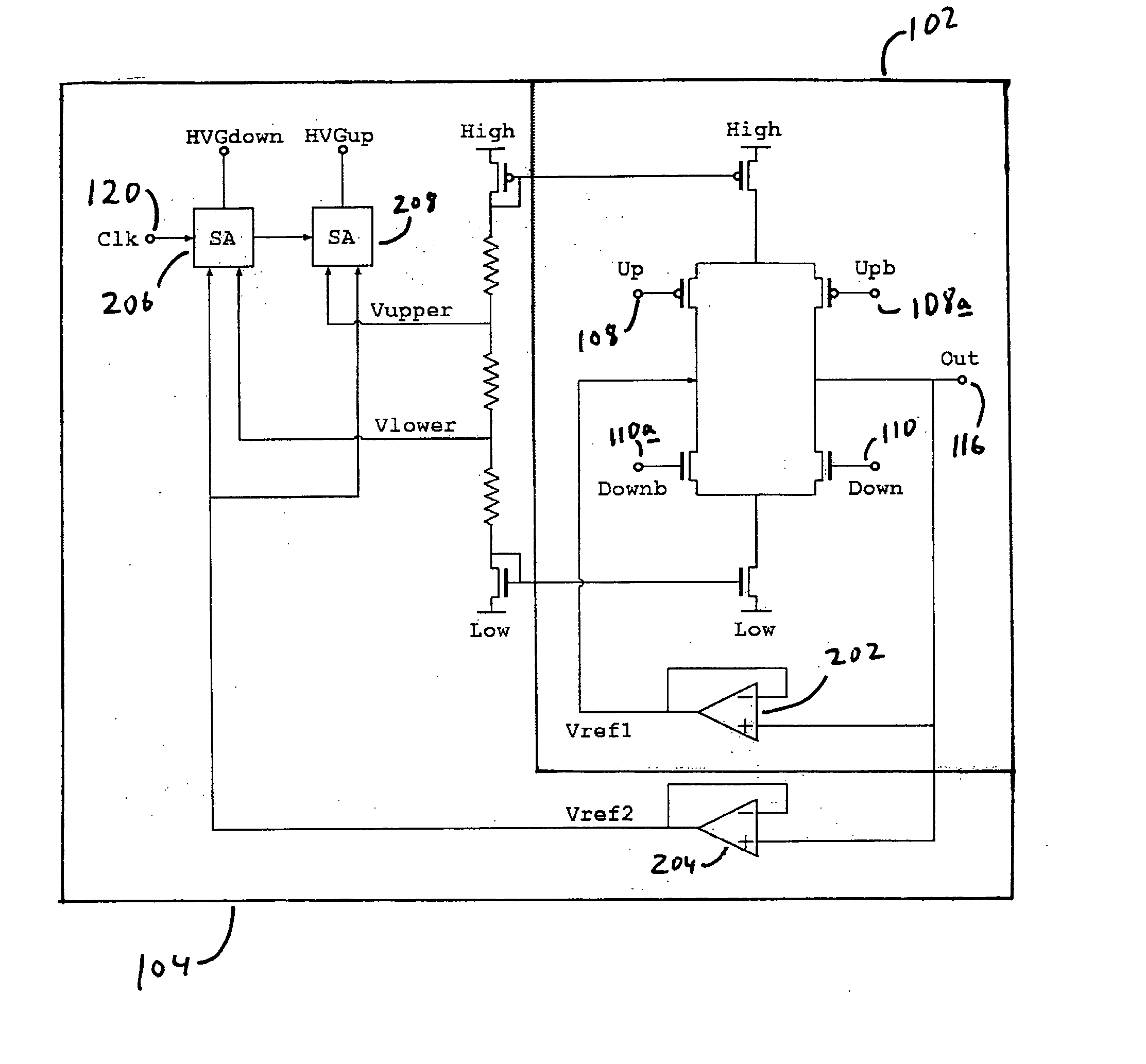
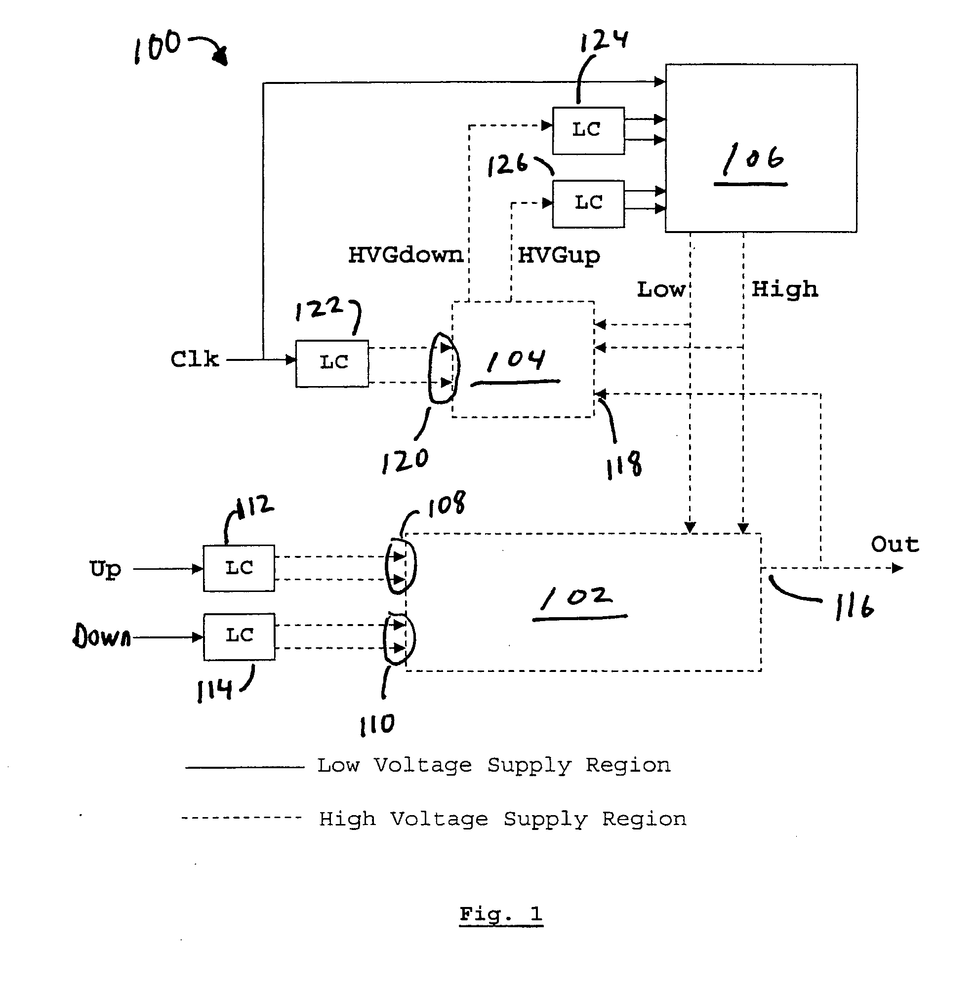
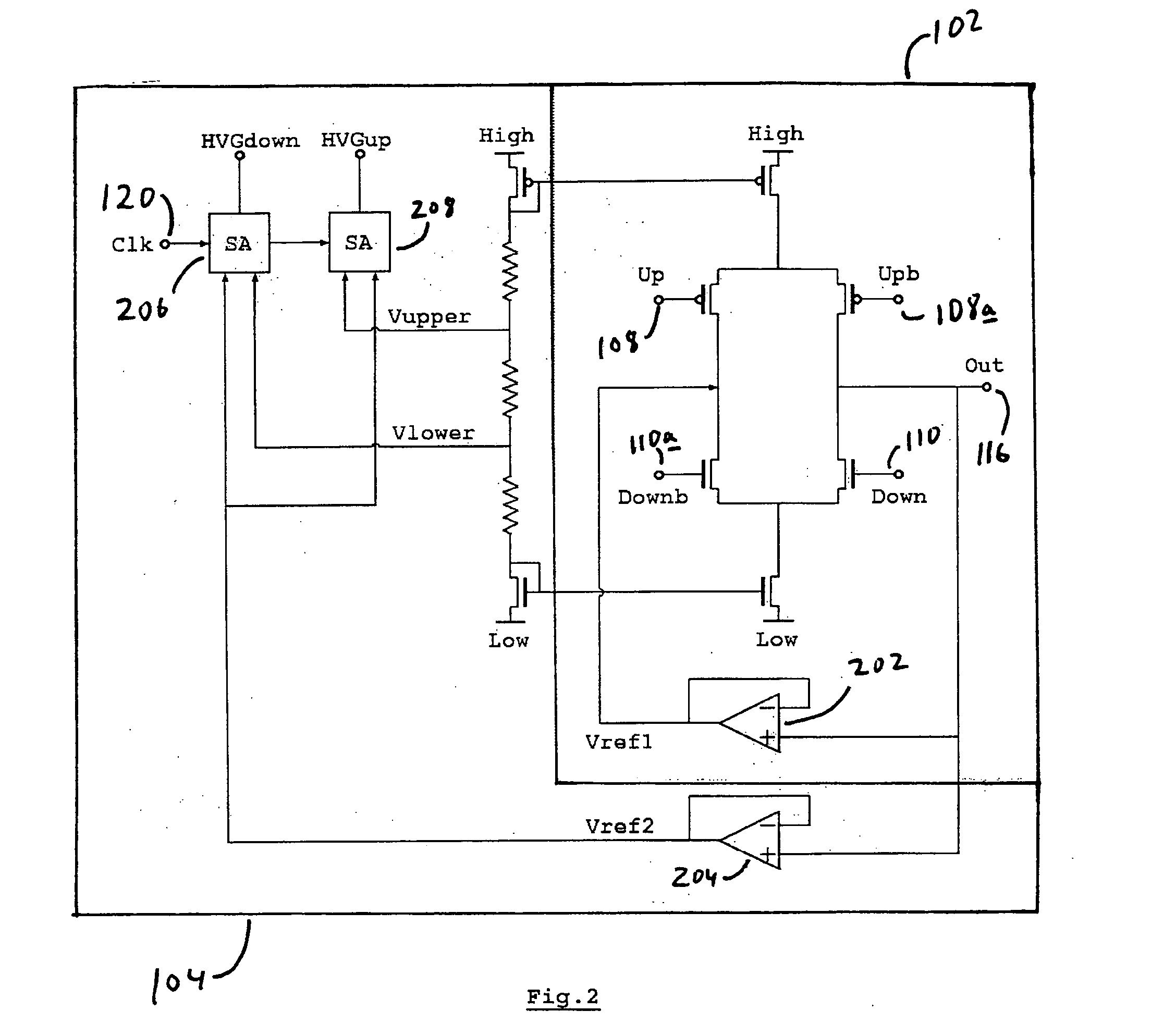
While embodiments of charge pump circuits are described generally with respect to a charge pump circuit for use with a MEMS variable capacitor, it will be appreciated that such circuits may be employed in other applications. However, in one embodiment, a control circuit portion of a charge pump circuit dynamically adjusts a power supply voltage (e.g., a tuning voltage) while only applying a limited voltage to an output stage of a high voltage control circuit. The circuit is implemented in a triple well technology, which is becoming increasingly more prevalent in CMOS processes with analog circuit options. The circuit does not employ any additional high voltage technology (e.g., processing steps) or devices. In such a circuit, the output voltage produced is limited by the N-well to substrate breakdown voltage of the particular manufacturing technology with which the charge pump is implemented. Such charge pump circuits may be used to implement a ‘power on demand’ power supply. The o...


PUM


Abstract

A charge pump circuit and method for supplying power. The charge pump circuit includes a first circuit receiving at least one low voltage signal and generating an output voltage signal. The charge pump circuit also includes a second circuit receiving a clock signal and the output voltage signal. The second circuit sends a request signal based on a comparison of the output voltage signal with two reference voltage signals, where the two reference voltage signals are derived from two supply voltage signals having a substantially constant potential difference. The charge pump circuit further includes a high voltage generator receiving the request signal and sending the two supply voltage signals to the first circuit and the second circuit. The high voltage generator adjusts the voltage potentials of the two supply voltage signals such that the voltage potential of the output voltage signal falls between the voltage potentials of the two reference voltage signals.

Description

BACKGROUND 1. Field This invention relates to circuits for supplying electrical power and, more specifically, relates to methods and apparatus for providing electrical power so as to increase the operating range of an electrical circuit. 2. Description of Related Art Tunable Micro Electro-Mechanical Systems (MEMS) devices appear more and more in RF circuits. For example, such devices are frequently implemented in wireless communication systems. Tunable MEMS allow for new functionality, or for improved performance of such systems (e.g. the performance of electrostatically tuned variable capacitors) as compared to previous approaches. The use of tunable MEMS devices provides for improving the linearity of tunable RF filters or enhancing the phase noise behavior of voltage-controlled oscillators. However, the tuning voltage required by such devices is typically between 5V and 50V, which is much higher than the maximum supply voltage of deep sub-micron complementary metal oxide semi...

Claims


Application Information

Patent Timeline
Patent Type & Authority Applications(United States)
IPC IPC(8): H03L7/089
CPCH03L7/0896H03L7/0895
Inventor INNOCENT, MANUEL
Owner INTERUNIVERSITAIR MICRO ELECTRONICS CENT (IMEC VZW)
Why Eureka
Try Eureka