Polyaxial bone screw with torqueless fastening

a bone screw and torqueless technology, applied in the field of spinal implant systems, can solve the problems of bone screw angular force, limited positioning, bone screw insertion, etc., and achieve the effect of reshaping the spine of a patient, preventing the disassembly of bone screw and toggle bol

Active Publication Date: 2005-03-31
SPINAL
View PDF51 Cites 339 Cited by
  • Summary
  • Abstract
  • Description
  • Claims
  • Application Information

AI Technical Summary

Benefits of technology

[0031] The present invention is fastening system for bone screws used in spinal fixation systems for reshaping the spine of a patient. The bone screw has threads on one end for anchoring in the spine. The other end has a spherical connector with a conical cavity therein. The cavity has the larger diameter base of the cone toward the threaded end of the screw and a narrower mouth. The mouth of the conical cavity accepts the spherical end of a toggle bolt such that the toggle bolt and the bone screw are connected by a ball joint. To prevent disassembly of the bone screw and toggle bolt, an associated split retention ring locking mechanism is inserted in the conical cavity between the spherical end of the toggle bolt and the mouth of the cavity. The resilient split retention ring can be compressed to reduce it's diameter for insertion through the mouth of the cavity and then expands to fill the conical cavity superior to the spherical end of the toggle bolt.

Problems solved by technology

Unfortunately, known spinal implant systems often correct one set of problems only to create new ones.
While bone screws are commonly used for anchoring, they are limited in their positioning due to the design of component pieces.
A problem with specially designed clamps is that bone structure cannot be determined until the patient's bone is exposed causing the necessity of a large inventory of various sized clamps to be on hand during surgery, of which the surgeon must search to find the right combination.
Even if a clamp combination is predicted, insertion of the screw may still require angular insertion due to muscle or tender nerve locations.
The result is a bone screw which exerts unpredictable forces upon attachment to component connectors.
Further, any movement of muscle and other tissue increases the difficulty of the operation and can be a major trauma to a person.
A problem with the screw is the need for the locking pin and the inability of the base screw to accommodate a threaded extension bolt.
Unfortunately, although these so-called “rigid screw” fixation systems can alter the curvature of a patient's spine, they can also be difficult to install.
As a result, the number of suitable anchoring locations is limited.
Achieving a proper fit between all of the components while contending with the constraints encountered during surgery is often difficult.
In severe cases, a suitable fit may not be achieved and the surgery will be unsuccessful.
Additionally, the nature of the installation process required for rigid screw fixation systems often subjects the system components to pre-loading that unduly stresses the interface between the patient's bone and the employed anchoring screws.
Corrective surgery to reattach anchoring screws exposes an already-weakened region to additional trauma and presents the risk of additional damage.
Unfortunately, some adjustable fixation systems tolerate only limited amounts of relative adjustment between components, operating best when loaded in one of several preferred arrangements.
Additionally, many adjustable fixation systems are prone to post-surgery component loosening.
As a patient moves about during day-to-day living, his spine is subjected to a seemingly-endless amount of dynamic loading.
Almost all activity requires some form of back motion; over time, this cyclic movement tends to work the components of many adjustable fixation systems loose.
Although capable of being locked in place, these systems are often difficult to secure, requiring an excess of tools during the installation process.
The need for extra tools, such as those required to shave, to apply anti-torque, or crimp key portions of a fixation system, increasing surgical risk by adding complexity and increasing the number of required steps.
Although locking-component fixation systems exist, many of them unduly increase the dangers of back implant surgery to an unacceptable level.
Additionally, many spinal fixation systems do not permit component repairs.
Often, such removal produces an undesirable “domino-effect,” requiring that several connectors be slid off to allow removal of the damaged connector.
Such requirements add unnecessary difficulty to an already-complex procedure.

Method used


Image

  • Polyaxial bone screw with torqueless fastening
  • Polyaxial bone screw with torqueless fastening
  • Polyaxial bone screw with torqueless fastening

Examples


Embodiment Construction

[0064] It is to be understood that while a certain form of the invention is illustrated, it is not to be limited to the specific form or arrangement of parts herein described and shown. It will be apparent to those skilled in the art that various changes may be made without departing from the scope of the invention and the invention is not to be considered limited to what is shown in the drawings and described in the specification.

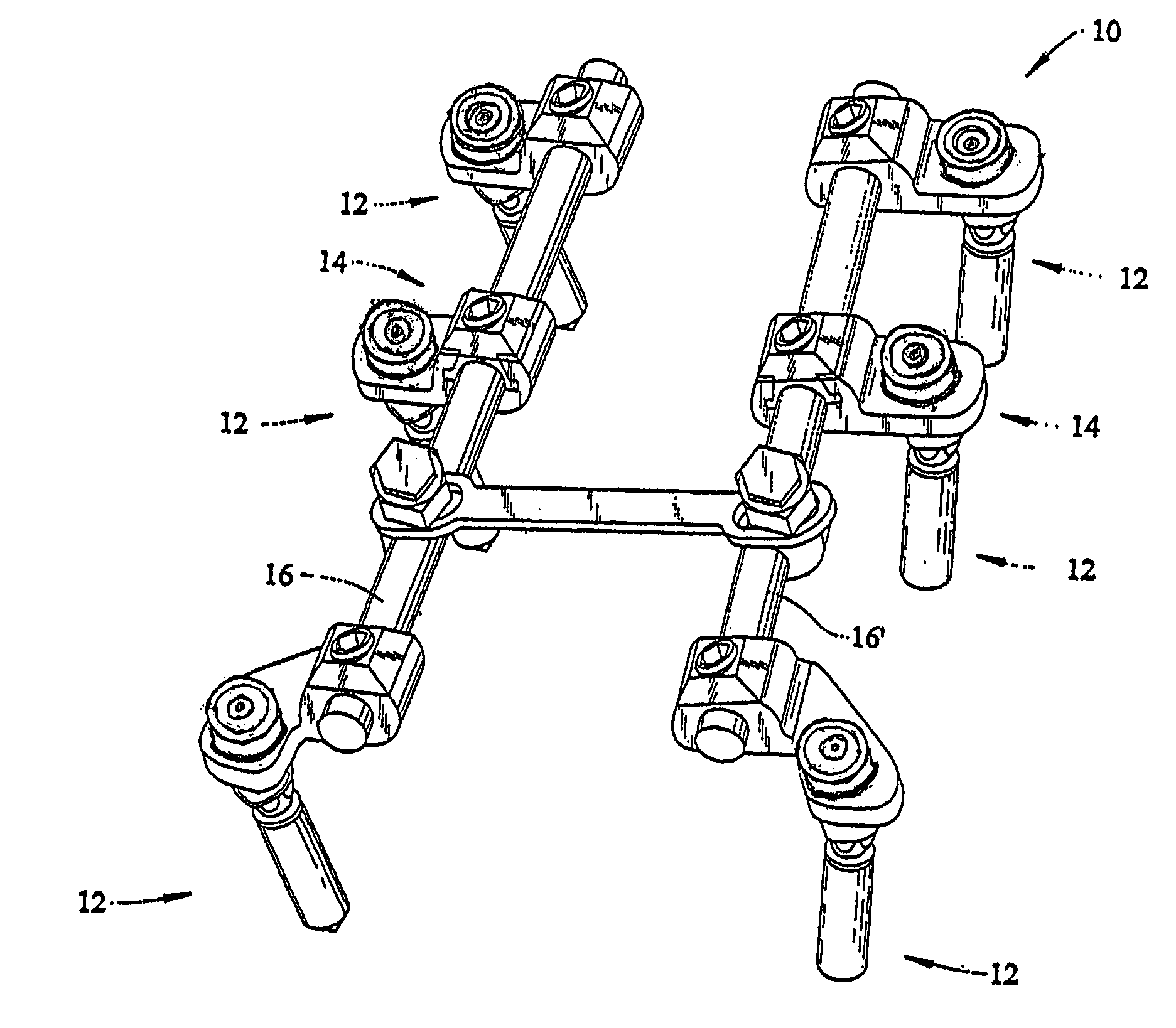
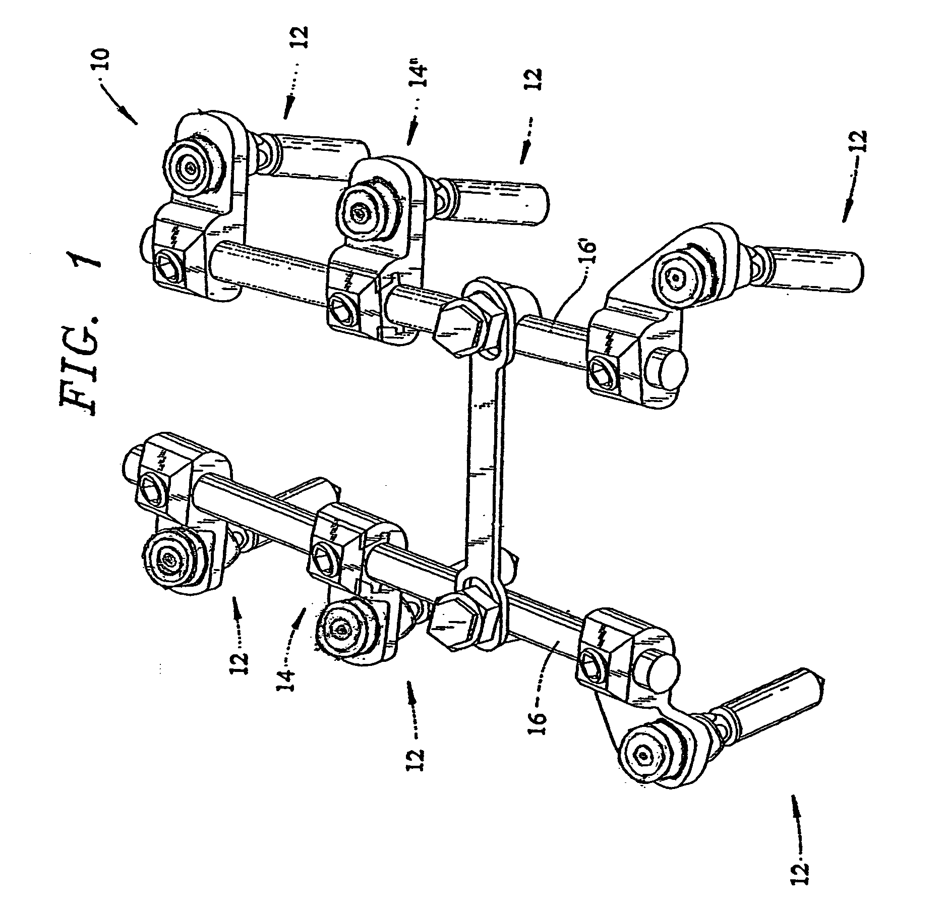
[0065] Now with reference to FIG. 1, the spinal fixation system 10 of the present invention is shown. By way of overview, the Fixation System 10 includes a collection of polyaxial bone-engaging anchoring assemblies 12 that are joined via connectors 14,14′ to stabilizing rods 16, 16′. The specifics of the spinal fixation system 10 will now be discussed in more detail.

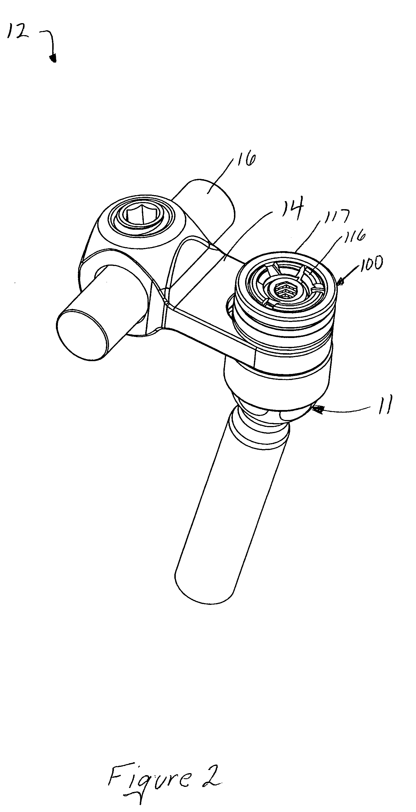
[0066] With additional reference to FIGS. 2 and 3, illustrate two common types of polyaxial anchoring assemblies 12 illustrated as the toggle bolt type polyaxial bone-screw 11 (FIG. 2) and th...


PUM


Abstract

An adjustable spinal fixation system is composed of a collection of anchoring assemblies attached, via a variety of connectors, to spine-stabilizing rods. The anchoring assemblies include a linking member attached in a ball-and-socket fashion to a bone-engaging member that is adapted to engage a spinal bone of a patient. The linking member joins one of the included connectors to an associated bone-engaging member. The connectors are selectively attached to one of the stabilizing rods. The anchoring assemblies each include a support collar and a split retention ring that cooperate to allow adjustment of the bone-engaging member and corresponding connector during surgery. When surgery is complete, a linear engaging fastener cooperates with the support collar and split retention ring to maintain the relative position of the entire fixation system, preventing unwanted movement between the system components.

Description

FIELD OF THE INVENTION [0001] This invention is directed to spinal implant systems and, in particular, to a multi-component adjustable implant system capable of maintaining a desired amount of torque between the skeletal bone and the implant. BACKGROUND OF THE INVENTION [0002] For individuals with spinal pathologies, the development of spinal fixation devices represents a major medical breakthrough. Surgically implanted fixation systems are commonly used to correct a variety of back structure problems, including those which occur as a result of trauma or improper development during growth. These fixation systems typically include one or more stabilizing rods aligned in a desired orientation with respect to a patient's spine. Additionally, anchoring screws are inserted into the patient's spinal bones, and a series of connectors is used to rigidly link the rods and anchors. [0003] A variety of designs exist, with each design addressing various aspects of the difficulties that arise wh...

Claims


Application Information

Patent Timeline
Patent Type & Authority Applications(United States)
IPC IPC(8): A61B17/70A61B17/88
CPCA61B17/7032A61B17/8869A61B17/7041A61B17/7035
Inventor DOUBLER, ROBERT L.HAMMILL, JOHN E.
Owner SPINAL
Why Eureka
Try Eureka