Method and device for drilling and tapping a bore for a bone screw

a bone screw and drill bit technology, applied in the field of bone screw drilling and drilling, to achieve the effect of facilitating bone screw insertion

Inactive Publication Date: 2005-03-31
ABERNATHIE DENNIS L
View PDF12 Cites 19 Cited by
  • Summary
  • Abstract
  • Description
  • Claims
  • Application Information

AI Technical Summary

Benefits of technology

[0004] The present invention relates to a novel drill-tap device and method for localizing, starting, drilling, and tapping the intended site of bone screw insertion in a single operation, using a single tool. By radiographic visualization, or other technique, the distal end of the drill-tap device is placed in the proper starting location on the surface of the bone, either by penetration of the skin for cutaneous procedures or by dissection to the surface of the bone for open procedures. The shaft of the drill-tap device is aligned in proper orientation. A tool, such as a hammer, is used to impact the proximal end of the drill-tap device, thereby driving the distal cutting tip of the drill-tap into the bone and creating a small bore in the bone at the desired location. The drill-tap device can be rotated by hand or with an instrument, such as a drill. By rotating the drill-tap device, the bore is enlarged and sized to the root diameter of the intended bone screw. As the drill-tap device progresses into the bone, the device cuts threads into the surface of the bore to facilitate bone screw insertion. The drill-tap is then removed and a bone screw is placed in the bore formed by the drill-tap device. Speed and reduced instrumentation are substantial advantages of this device. Also, by drilling and enlarging the bore with a single device, correction of alignment may be achieved before the final bore is made.

Problems solved by technology

Further, the device tends to direct itself toward the intended hole orientation.

Method used


Image

  • Method and device for drilling and tapping a bore for a bone screw
  • Method and device for drilling and tapping a bore for a bone screw

Examples


Embodiment Construction

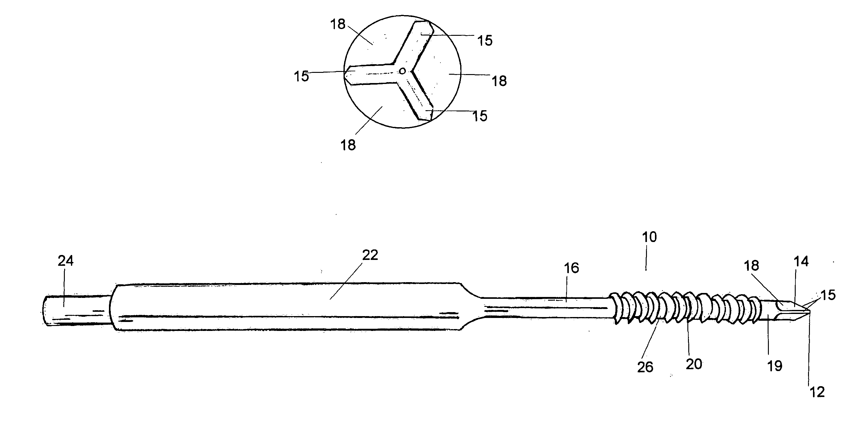
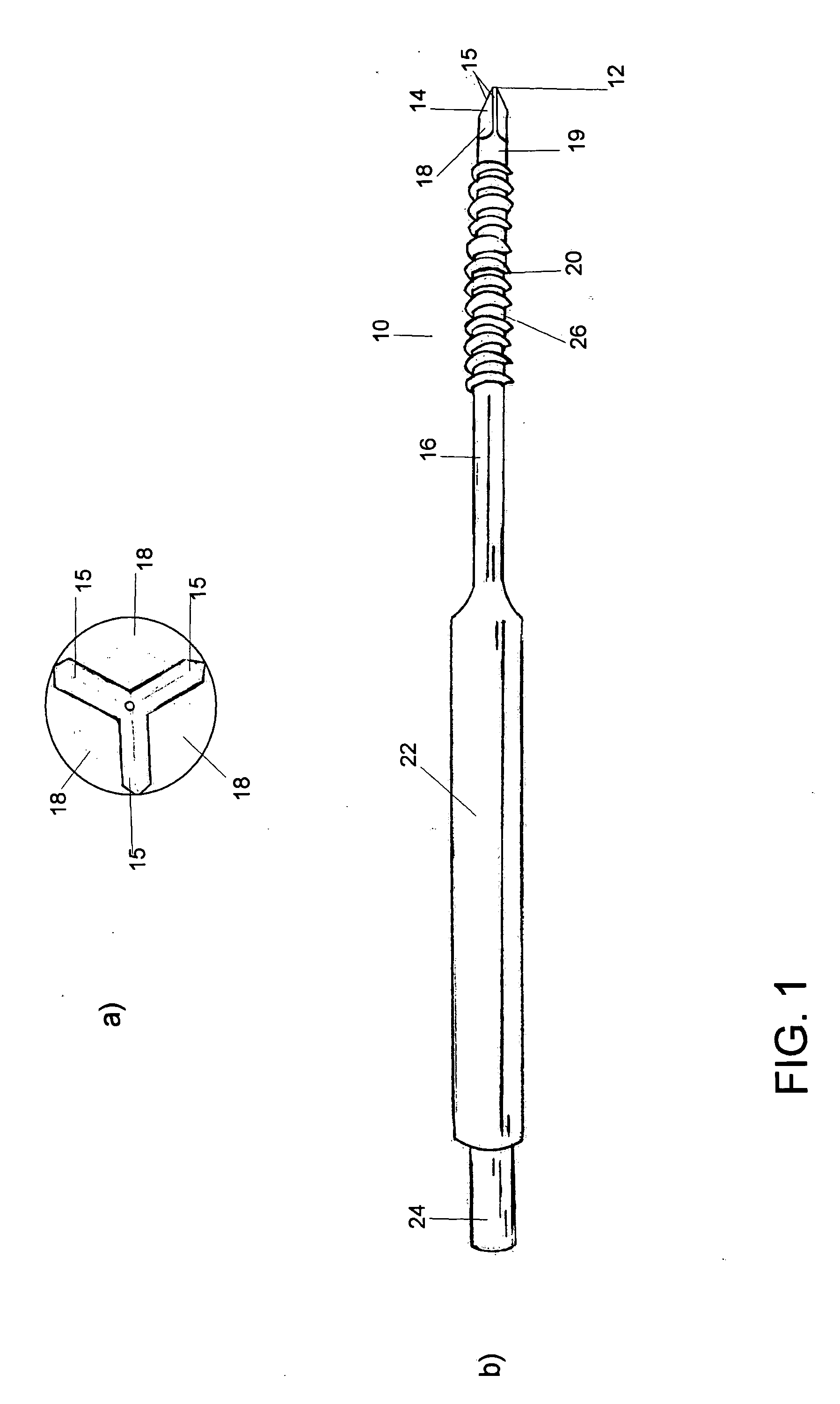
[0010] Referring now to the drawings, wherein like numeral indicate like parts, the numeral 10 refers generally to a device constructed in accordance with the teachings of the present invention. Drill-tap device 10 has a generally pyramid-shaped drill tip 14, formed of three cutting edges or flanges 15. Although a pyramid-shape with three flanges is shown in the drawings, this arrangement is exemplary of one embodiment of the present device. It is contemplated that other arrangements, such as a traditional bayonet-point or other geometry, including multiple flanges, could also be used.

[0011] A point 12 at the distal end of device 10 is designed to penetrate bone and initiate a bore therein. After the shaft 16 of drill-tap device 10 is aligned in the proper direction, a force from a tool such as a hammer is applied against the proximal end of drill-tap device 10, thereby driving distal point 12 into the bone and creating a small bore in the bone at the desired location. By rotating ...


PUM


Abstract

The present invention is directed to a device for drilling and tapping a bore for receiving a bone screw. The device includes a drill tip portion for creating a bore, a threaded shank portion for creating female threads within the bore so that the bore can receive a bone screw, and a handle or attachment portion for the purpose of manipulating the device. The present invention is also directed to a method of using the device.

Description

CROSS REFERENCE TO RELATED APPLICATIONS [0001] This Application claims benefit of U.S. Provisional Application No. 60 / 505,777, filed Sep. 25, 2003.BACKGROUND OF THE INVENTION [0002] Bone screws are often used for stabilizing bones, internal fixation of fractures, and attaching orthopaedic implants. Bones screws are generally made of metallic material, such as titanium, cobalt-chrome alloys, and stainless steel. The orthopaedic procedure for starting, drilling, and tapping a hole for insertion of a bone screw typically involves a number of steps. Once the site for the bone screw is visualized, a surgeon will expose the fracture or osteotomy site. With the advent of x-rays and other visualization techniques, the exposure area required to place a bone screw may be reduced and thus the procedure can be done percutaneously. When percutaneous or other exposures are used, the procedure often begins with the placement of a guide wire at the intended screw bore location to provide a referenc...

Claims


Application Information

Patent Timeline
Patent Type & Authority Applications(United States)
IPC IPC(8): A61B17/16
CPCA61B17/1655
Inventor ABERNATHIE, DENNIS L.
Owner ABERNATHIE DENNIS L
Why Eureka
Try Eureka