
Data storage subsystem

a data storage and subsystem technology, applied in the field of data storage systems, can solve the problems of inability to keep updating order, inability to update order, so as to eliminate complicated exchanges of attribute information and achieve higher error resistance properties

Inactive Publication Date: 2005-03-31
HITACHI LTD
View PDF17 Cites 63 Cited by
  • Summary
  • Abstract
  • Description
  • Claims
  • Application Information

AI Technical Summary

Benefits of technology

[0015] To make both of original and copied attribute information match completely as described above, the resynchronization must be achieved between both original and copied information, for example, after a remote-copy operation, stopped once, then restarted or after the copy direction is changed. To achieve the resynchronization, a difference of attribute information generated between those two operations is copied while the host computer does not know it in the embodiment of the present invention, thereby the attribute information is resynchronized quickly.
[0016] Recently, some users come to expect using of the above described functions for remote-copying over a plurality of data storage subsystems to improve the error resistance. The embodiment of the present invention also realizes the reinote copying.
[0021] According to the present embodiments, attribute information can be copied to a back-up data storage subsystem, so that the back-up side subsystem uses the attribute information automatically without intervention from the host computer. This eliminates complicated exchanges of attribute information between the host computers associated with the source subsystem and the destination subsystem.
[0022] Furthermore, according to the present embodiments, data and attribute information can be transferred to a destination data storage subsystem synchronously, i.e., in the order issued by the host computer, so that the data and the attribute information in the duplicate side subsystem can be updated with the received data and attribute information fast without the host computer involvement. If a difference occurs in any attribute information between stop of a remote-copy and restart of the remote-copy and / or between a forward remote-copy and its backward remote-copy, only the difference is copied. Without requiring the host computer involvement. Attribute information can thus be re-synchronized quickly between those stop and restart operations.
[0023] In addition, attribute information can be copied among a plurality of data storage subsystems, which makes it easier to remote-copy the attribute information among the plurality of data storage subsystems, thereby a system with higher error resistance properties can be formed more easily.

Problems solved by technology

The copy operation has thus been complicated.
This is why basically the updating order cannot be kept between attribute updating and data updating, although the updating order has been achieved with difficulty when the program in the subject host computer manages the order in close cooperation with the subject data storage subsystems.
However, the cooperation is not only difficult, but also comes to generate a large overhead.

Method used


Image

  • Data storage subsystem
  • Data storage subsystem
  • Data storage subsystem

Examples


first embodiment

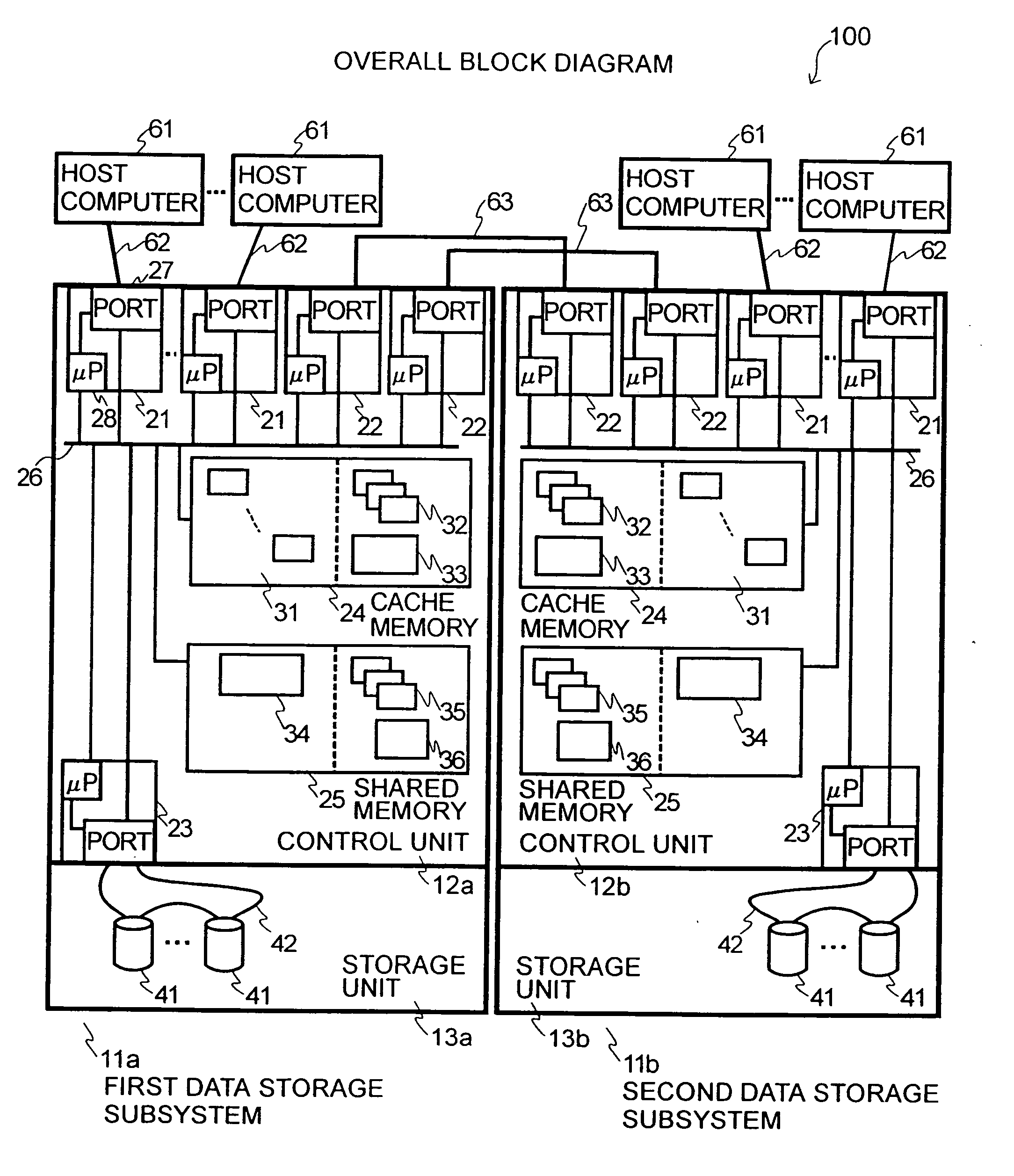
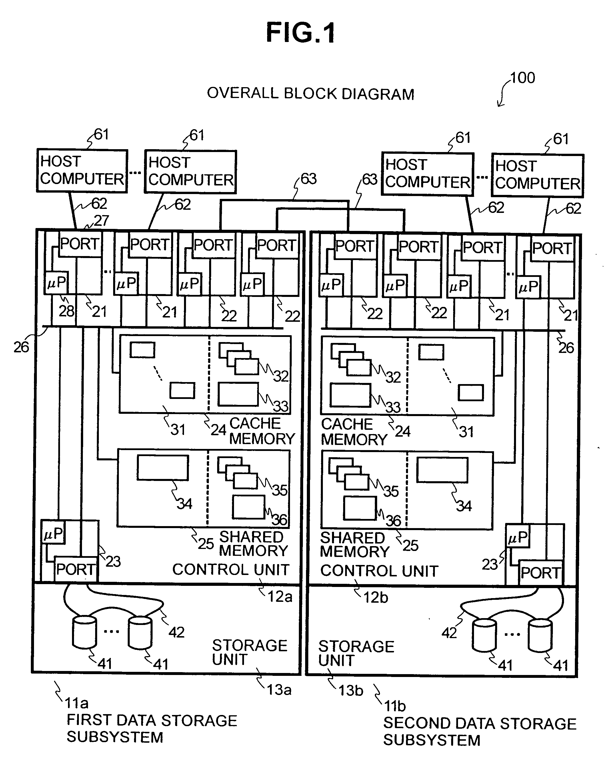
[0042]FIG. 1 shows a schematic block diagram of a computer or data storage system (or storage system) 100 according to a first embodiment of the present invention. The storage system 100 includes a first storage subsystem 11a and a second storage subsystem 11b (The storage subsystems (also referred to simply as “subsystems”) 11a and 11b are connected to each other through a communication link or data path 63 to exchange information. The subsystems may be disposed closely to each other, i.e., within the same building or room, or far away from each other, e.g., in different cities.

[0043] Each subsystem 11a, 11b is connected to a plurality of host computers 61 through a host access bus 62. Each subsystem 11a, 11b includes a storage controller 12 (or control unit 12) used to handle data read / write requests and a storage unit 13 including a recording medium for storing data in accordance with write requests.

[0044] The control unit 12 includes a host channel adapter 21 coupled to a host...

second embodiment

[0086]FIG. 8 illustrates a storage system 150 according to a second embodiment of the present invention. The storage system 150 includes first, second, third, and fourth data storage subsystems 11a to 11d. For illustrative purposes, the same numbers as in FIG. 1 are used for similar devices and components in the system 150. The control unit 12, the storage unit 13, the disk adapter 23, as well as the port 27 and the microprocessor 28 in each adapter, the magnetic disk drive 41, and the disk input / output path 42 are similar to those in the first embodiment. The description for those items will thus be omitted here. In this embodiment, a data path 63 is used for the connection among the first, second, and third subsystems 11a, 11b, and 11c, as well as between the third and fourth subsystems 11c and 11d. In this configuration, a logical volume used by the host computer connected to the first storage subsystem 11a can be remote-copied to other three destination subsystems (the second, t...


PUM


Abstract

A method for copying information from a first storage subsystem to a second storage subsystem is disclosed. The first and second storage subsystems are provided in a data storage system. The method comprises transmitting first data block from the first storage subsystem to the second storage subsystem, the first storage subsystem being associated with a first host computer and the second storage subsystem being associated with a second host computer; and transmitting first attribute information from the first storage subsystem to the second storage subsystem without intervention from the first host computer.

Description

CROSS-REFERENCES TO RELATED APPLICATIONS [0001] The present application is related to and claims priority from Japanese Patent Application No. 2002-163705, filed on Jun. 5, 2002. BACKGROUND OF THE INVENTION [0002] The present invention relates to a data storage system including a plurality of storage subsystem and a method of storing data therein. [0003] In recent years, the computer storage systems are configured to handle a huge amount of data. In addition, data is updated very frequently in these computer systems. A method for backing up large amounts of data and restoring a system to its normal state when an error occurs are important concerns in this technology field. One method used to address this concern has been a remote-copying technique. According to the technique, the data storage subsystems (external storage units), each having a magnetic disk array, are disposed away from each another. These data storage subsystems are then connected to each another through a communica...

Claims


Application Information

Patent Timeline
Patent Type & Authority Applications(United States)
IPC IPC(8): G06F3/06G06F12/00G06F17/30
CPCG06F3/061G06F3/0619G06F3/065Y10S707/99955G06F11/2058G06F11/2071Y10S707/99953G06F3/067
Inventor OHNO, HIROSHIURABE, KIICHIRONAKANO, TOSHIOTABUCHI, HIDEO
Owner HITACHI LTD
Learn More