Hydrogen storage container

a technology for storage containers and hydrogen, applied in the direction of gas/liquid distribution and storage, containers, large containers, etc., can solve the problems of localized stress on the container, decrepitation of metal hydride particles, etc., and achieve the effect of preventing ingress

Inactive Publication Date: 2005-04-07
HERA HYDROGEN STORAGE SYST
View PDF26 Cites 11 Cited by
  • Summary
  • Abstract
  • Description
  • Claims
  • Application Information

AI Technical Summary

Benefits of technology

[0004] The present invention provides a container configured for containing metallic particles, the metallic particles capable of absorbing hydrogen such that the metallic particles expand upon the absorption of hydrogen, the container including an inner surface, comprising a liner disposed within the container such that a void space is provided between the liner and the inner surface, wherein the liner engages the inner surface to substantially prevent ingress of metallic particles, when the metallic particles are contained in the container, into the void space.

Problems solved by technology

Repeated absorption and desorption cycles typically result in the decrepitation of the metal hydride particles.
Such increase in packing fraction, coupled with particle expansion during absorption, potentially creates localized stresses on the container.

Method used


Image

  • Hydrogen storage container
  • Hydrogen storage container
  • Hydrogen storage container

Examples


Embodiment Construction

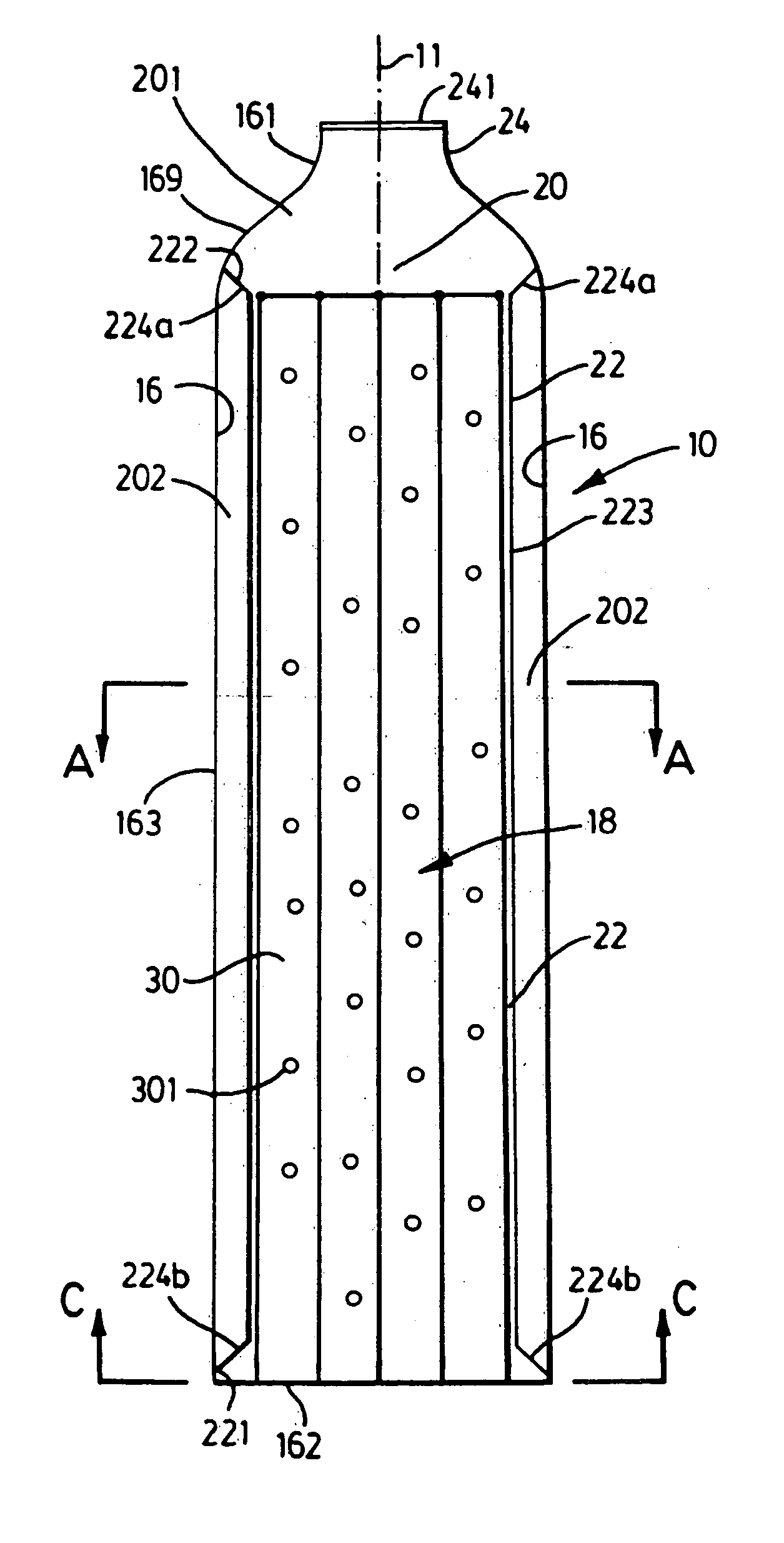
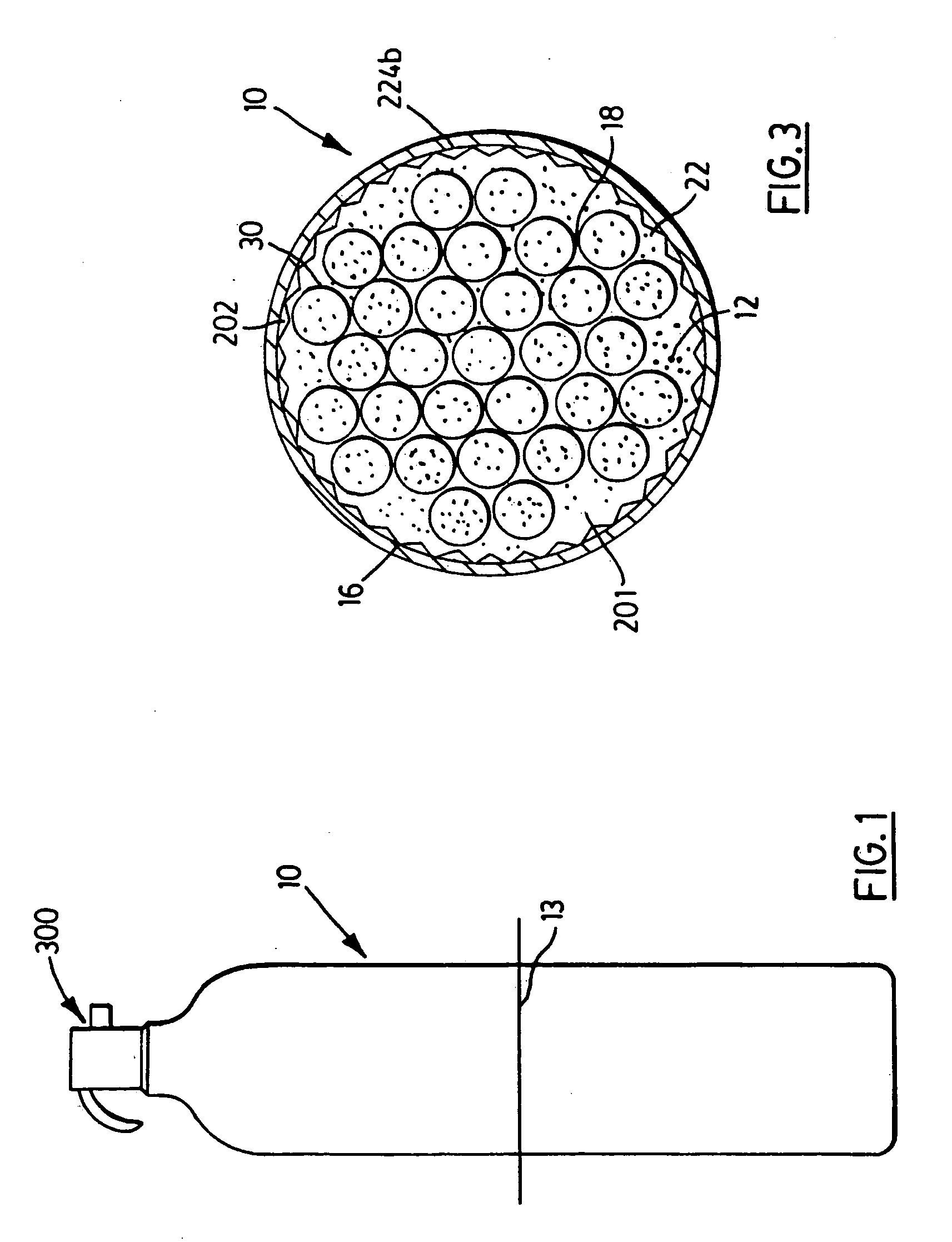
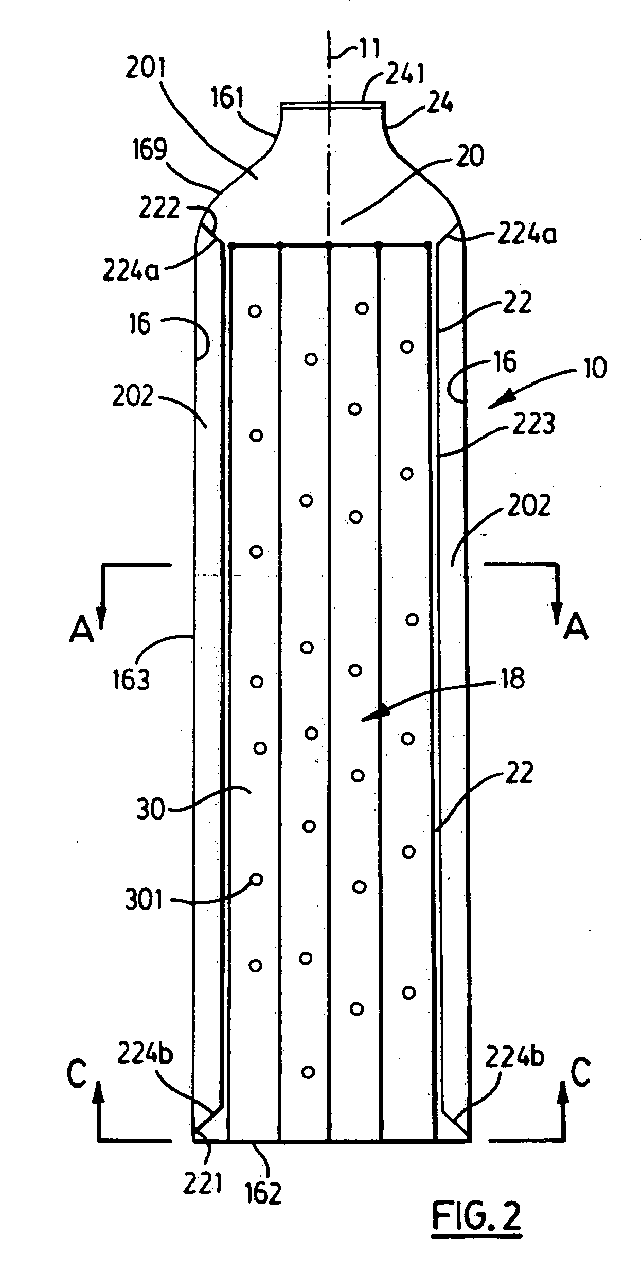
[0052] Referring to FIGS. 1 and 2, the present invention provides a container 10 for containing metallic particles 12 capable of forming metal hydrides.

[0053] The interior space 20 of the container 10 receives metallic particles 12 capable of forming metal hydrides. The metallic particles 12 are in the form of a powder. An example of a suitable particle size of the powder is within the range of one micron to 3000 microns. The metallic particles 12 must be capable of absorbing hydrogen (also known as “charging”) to effect storage of hydrogen in the form of a metal hydride. Further, such metallic particles 12, after having absorbed hydrogen, (in the form of a metal hydride) must be capable of desorbing hydrogen (also known as “discharging”) upon demand from an unit operation, such as when required for use as a fuel in a fuel cell or in an internal combustion engine. Upon absorbing hydrogen, the metallic particles 12 expand, and thereby increase the volume occupied. During desorption,...


PUM

PropertyMeasurementUnit
particle sizeaaaaaaaaaa
yield strengthaaaaaaaaaa

Abstract

A container configured for containing at least metallic particles, the metallic particles capable of absorbing hydrogen such that the metallic particles expand upon the absorption of hydrogen, the container including an inner surface, comprising: a liner disposed within the container such that a void space is provided between the liner and the inner surface, wherein the liner engages the inner surface to substantially prevent ingress of metallic particles, when the metallic particles are contained in the container, into the void space. A method of assembling a container for containing metallic particles capable of absorbing hydrogen is provided and comprises a container including an inlet and an inner surface defining a container space, rolling a magnetically responsive liner about a mandrel so that the liner assumes a spiral configuration about the mandrel, when the liner is rolled about the mandrel inserting the liner into the container space through the inlet, releasing the liner from the mandrel, removing the mandrel from the container space through the inlet, applying a magnetic force sufficient to urge the liner against the inner surface of the container, when the magnetic force is acting on the liner, inserting a plurality of tubes into the container space through the inlet so as to urge the liner into engagement with the inner surface so as to define (i) a storage space configured to contain the metallic particles and (ii) a void space configured to contract as the metallic particles expand upon the absorption of hydrogen, terminating the application of the magnetic force, and inserting a plurality of metallic particles into the storage space.

Description

FIELD OF THE INVENTION [0001] The present invention relates to hydrogen storage containers and, particularly, to containers for containing metallic particles capable of forming metal hydrides. BACKGROUND OF THE INVENTION [0002] Metal hydrides, in the form of metallic particles, are used to store hydrogen in many different sizes and shaped containers. In order to facilitate the charging and discharging of the hydrogen, the metal hydride and, consequently, the container, needs to be cooled or heated. To facilitate good performance of the container (desorption rate, filling time, etc.), the inside of the container requires efficient heat exchange means to improve the charging / discharging kinetics. [0003] Repeated absorption and desorption cycles typically result in the decrepitation of the metal hydride particles. By virtue of the decrepitation, a localized increase in packing fraction of the metallic particles is observed. Such increase in packing fraction, coupled with particle expan...

Claims


Application Information

Patent Timeline
Patent Type & Authority Applications(United States)
IPC IPC(8): B65D81/28F17C11/00
CPCF17C11/002F17C11/005Y02E60/321F17C2209/2163F17C11/007
Inventor GAGNON, FREDERICSCHULZ, ROBERTLAROCHELLE, PATRICKGENDRON, STEPHANE
Owner HERA HYDROGEN STORAGE SYST
Why Eureka
Try Eureka