Scatter correction device for radiative tomographic scanner

a radiation correction and scanner technology, applied in the field of radiation tomographic scanner apparatus and method, can solve the problems of reducing system spatial resolution, ignoring source location, and difficult to correct scattered radiation in pet, so as to improve the accuracy of experimental results, improve contrast, and improve the effect of accuracy

Inactive Publication Date: 2005-04-07
NATIONAL TSING HUA UNIVERSITY
View PDF4 Cites 21 Cited by
  • Summary
  • Abstract
  • Description
  • Claims
  • Application Information

AI Technical Summary

Benefits of technology

The present invention has been made to overcome the scatter correction problems for conventional tomographic scanners. The primary object is to provide a scatter correction device and method being applied to all tomographic scanners that use ra...

Problems solved by technology

The correction of the scattered radiation in PET is one of the most challenging tasks.
Scattered events cause the misjudgment of source location and downgrade system's spatial resolution.
Rejection of scattered photons on the basis of energy discrimination has limited performance because the use of relatively wide energy window to maintain accurate counting statistics.
Many of these parameters are non-stationary, which implies a potential difficulty when developing proper scatter correction techniques.
Accurate scatter correction is one of the major problems facing quantitative 3D PET and still is an open question.
The use of a constant scatter ratio for larger objects might not be adequate.
As a re...

Method used


Image

  • Scatter correction device for radiative tomographic scanner
  • Scatter correction device for radiative tomographic scanner
  • Scatter correction device for radiative tomographic scanner

Examples


Embodiment Construction

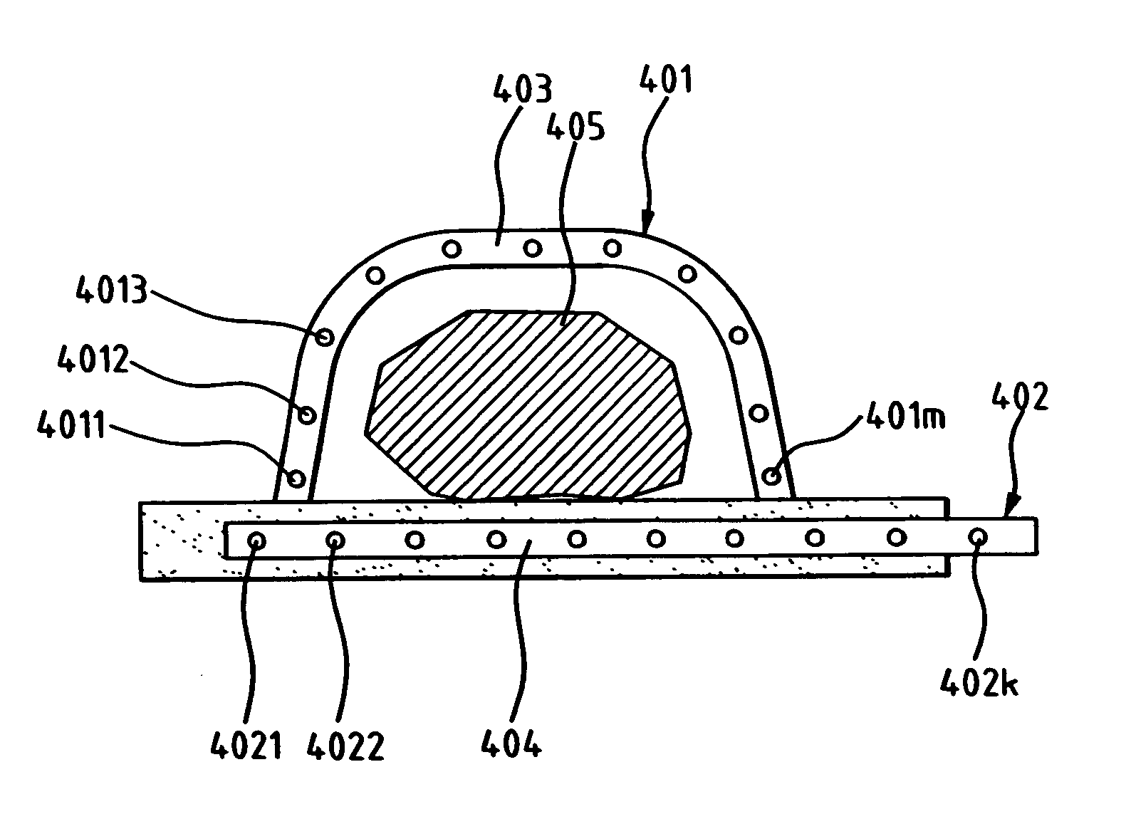
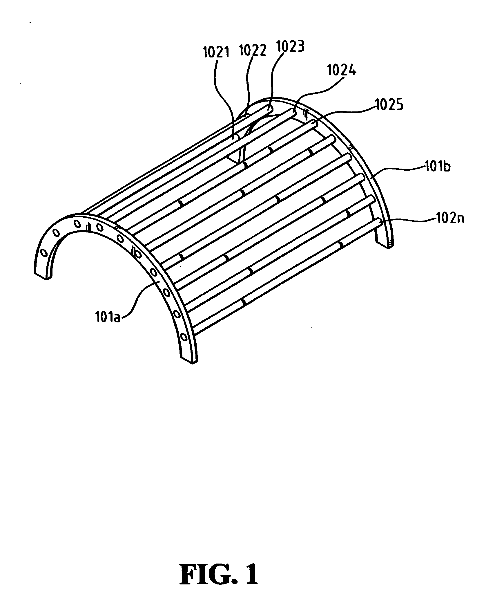
FIG. 1 illustrates a scatter correction device according to the present invention. Referring to FIG. 1, the scatter correction device is mainly formed with one or more beam stoppers 1021, 1022, 1023, 1024, 1025, . . . , 102n, and one or more steady support components 101a and 101b. Each beam stopper has a thickness from the range of 2 mm to 5 mm, and the two ends fixed on the steady support components respectively. With such ends, these beam stoppers can be sustained at fixed locations by the steady support components.

The use of the beam stoppers is used to block radiation efficiently. Because high Z materials have great blocking ability, the beam stoppers of the invention can be thin sticks made of high Z materials, as shown in FIG. 1. The high Z materials may include lead and wolfram. According to the experimental results, the beam stoppers with thickness equal to 3 mm can block radiation most efficiently. When the scatter correction device is applied to a SPECT, due to the lower...


PUM


Abstract

A scatter correction device for radiative tomographic scanners is disclosed. The device comprises at least one steady support component and multiple beam stoppers made of high Z materials such as lead and wolfram. Each beam stopper has two ends fixed on the steady support component respectively. Theses beam stoppers can thus be sustained at fixed locations by the steady support component. During scanning an object, the device is placed between the object and detectors. But when the scatter correction device is applied to a CT scanner, the device is placed between object and radiation source. It attenuates part of the primary radiation with very small affects on the scattered radiation.

Description

FIELD OF THE INVENTION The present invention relates generally to an apparatus and method for radiative tomographic scanners, and more specifically to a scatter correction device and method for radiative tomographic scanners. The device and method can be applied to emission type scanners: PET (positron emission tomography) and SPECT (single photon emission tomography) and transmission type scanner: CT (computed tomography). BACKGROUND OF THE INVENTION Due to the high resolution and sensitivity, the emission tomographic scanner is becoming the instrument of choice in human functional study. The strength of the tomographic scanner is its ability to qualify the activity distribution of radionuclides in the human body. The accuracy of the quantification depends on an adequate correction of the raw data. In the following, a PET system is used as an example for illustration purpose. Attenuation and scatter corrections in PET are considered by the nuclear medicine community as a vital c...

Claims


Application Information

Patent Timeline
IPC IPC(8): G01T1/164G01T1/29
CPCG01T1/2985G01T1/1648
Inventor CHUANG, KEH-SHIHWU, JAYJAN, MEEI-LING
Owner NATIONAL TSING HUA UNIVERSITY
Why Eureka
Try Eureka