Small-sized motor

a small-sized, motor technology, applied in the direction of dynamo-electric machines, electrical equipment, supports/enclosements/casings, etc., can solve the problems of motor failure, increase in the number of parts, and assembly work required

Active Publication Date: 2005-04-07
SANYO SEIMITSU
View PDF5 Cites 18 Cited by
  • Summary
  • Abstract
  • Description
  • Claims
  • Application Information

AI Technical Summary

Benefits of technology

[0008] A first object of the present invention is to provide a small-sized motor of a structure not requir...

Problems solved by technology

However, the above vibration motor has had the following problems:
There, an increase in the number of parts and troublesome assembly work are required and the production cost becomes higher.
Further, since the metal holder frame has a pair of bent spring-holding pieces for gripping the vibration motor body and these stick out from the level bottom, extra board mounting area is consumed.
(2) Further, the pla...

Method used


Image

  • Small-sized motor
  • Small-sized motor
  • Small-sized motor

Examples


Embodiment Construction

[0030] Preferred embodiments of the present invention will be described in detail below while referring to the attached figures.

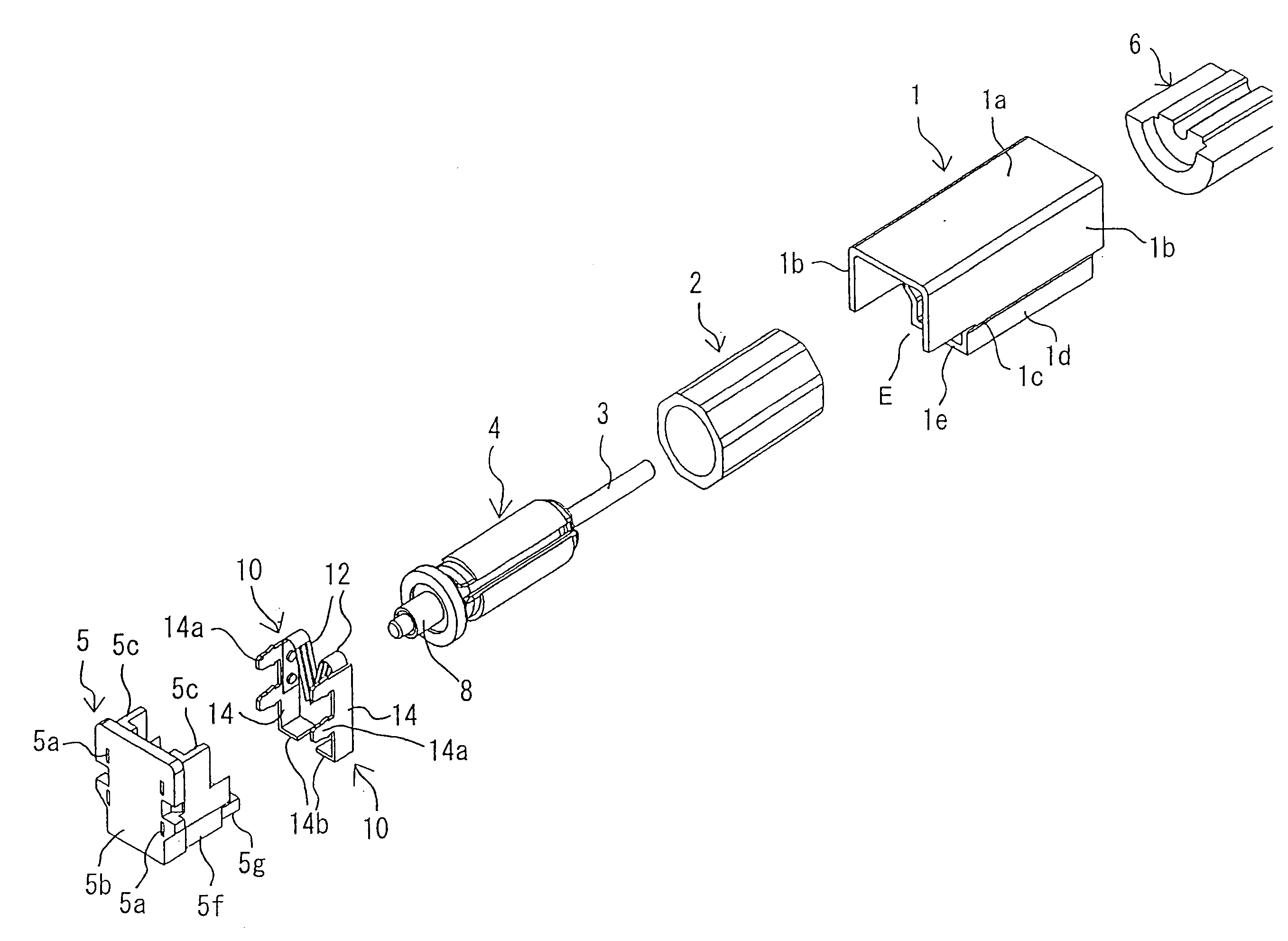
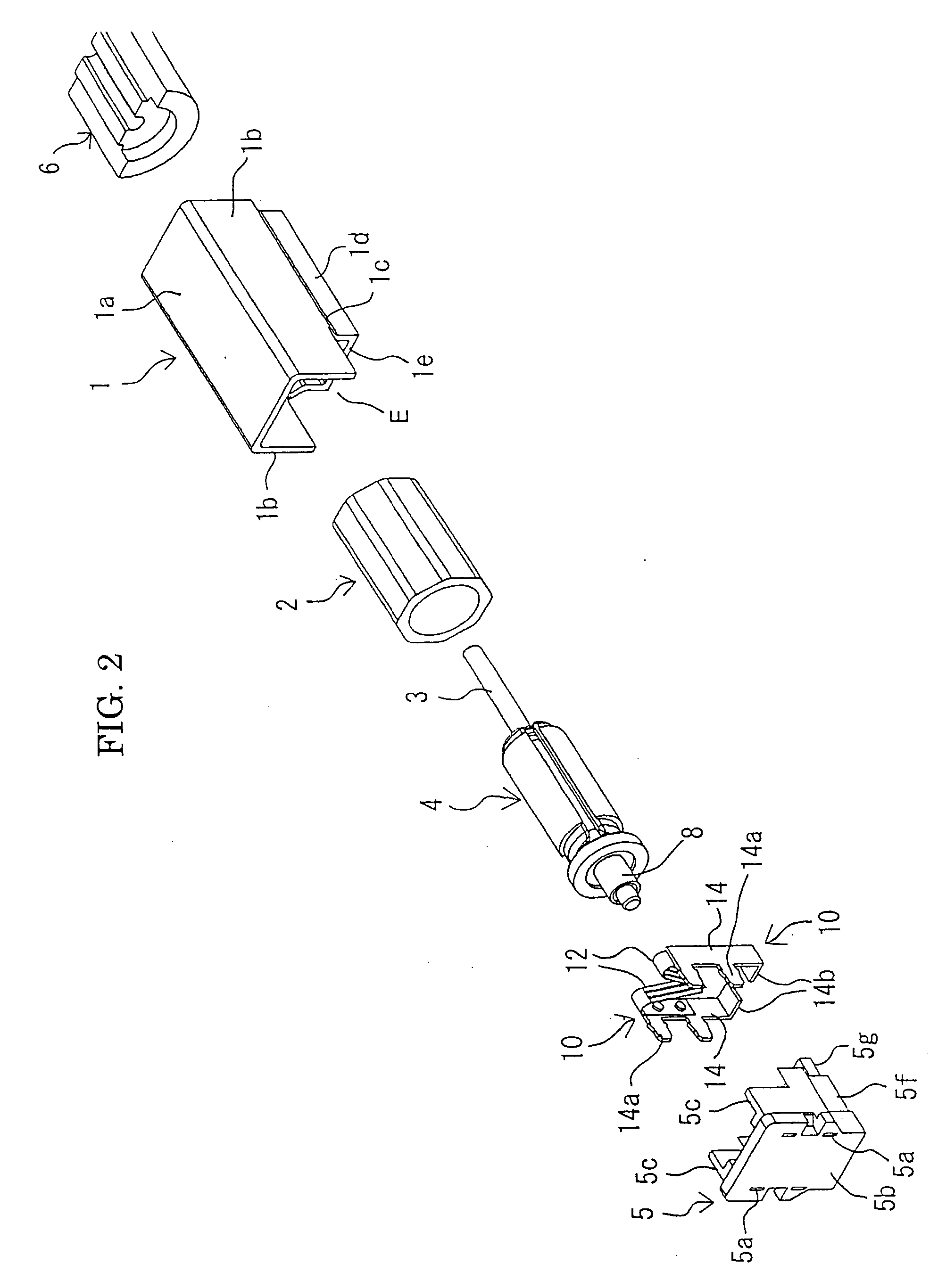
[0031] To achieve the first object, the present invention provides a small-sized motor having a motor case provided with a permanent magnet at an inner surface and rotatably holding a motor shaft carrying an armature via a bearing and a plastic end cap fit into an opening at one end side of the motor case and having a pair of brush assemblies attached. This is characterized by the special structure of the motor case.

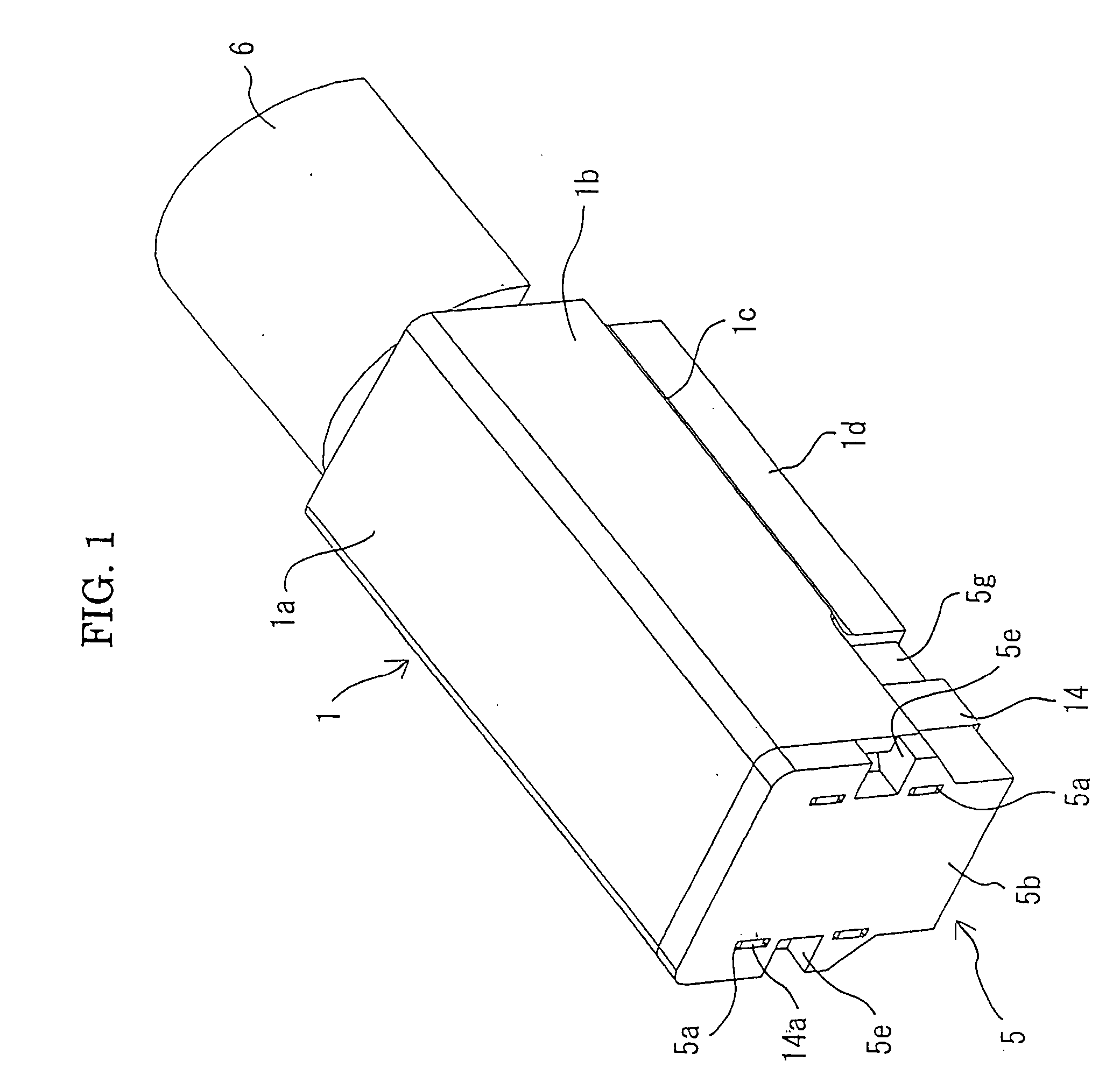
[0032] The motor case is comprised of a level flat part, a pair of left and right symmetric side parts bent from that level flat part, and a level bottom part connecting the bottom ends of the pair of side parts and substantially parallel to the level flat part.

[0033] If using a motor case of this structure, it is possible to bond the level bottom part to the bonding patterns of a printed circuit board by coating cream solder, so it is possib...


PUM


Abstract

A small-sized motor of a structure not requiring any metal holder frame in a surface mounting process to a printed circuit board by reflow soldering, wherein the motor case is provided with a level flat part, a pair of left and right first side parts bent downward from this substantially perpendicularly and parallel to each other, a pair of left and right second side parts bent inward from these at an inclination of about 45°, and a pair of left and right third side parts bent down from these and parallel to each other, and a level bottom part connecting these bottom ends and extending substantially parallel to the level flat part.

Description

BACKGROUND OF THE INVENTION [0001] 1. Field of the Invention [0002] The present invention relates to a vibration motor, fan motor, or other small-sized motor, more particularly relates to a small-sized motor of a structure suitable for surface mounting on a printed circuit board by reflow soldering. [0003] 2. Description of the Related Art [0004] As a vibration motor of a structure suitable for surface mounting on a printed circuit board, as disclosed in Japanese Patent Publication (A) No. 11-234943, there is known one having a vibration motor body with an eccentric weight attached to a motor shaft, a metal holder frame provided with a motor holder for holding a motor case fit into it, and a pair of external connection terminals (motor terminals) attached to a plastic end cap for closing an opening of one end of the motor case. The level bottom of the metal holder and the pair of external connection terminals are bonded with bonding patterns and power supply patterns formed on a pri...

Claims


Application Information

Patent Timeline
IPC IPC(8): H02K5/00H02K5/22H02K7/06H02K5/04
CPCH02K5/00H02K2211/03H02K7/061H02K5/225
Inventor TAKAGI, TAKAHIROYAMADA, YUUKI
Owner SANYO SEIMITSU
Why Eureka
Try Eureka