
Device and method for identifying a component surrounded by an outer package

a technology of components and outer packages, applied in the field of identifying components surrounded by external packages, to achieve the effect of increasing the information density of information elements

Active Publication Date: 2005-04-07
SIEMENS HEALTHCARE GMBH
View PDF4 Cites 5 Cited by
  • Summary
  • Abstract
  • Description
  • Claims
  • Application Information

AI Technical Summary

Benefits of technology

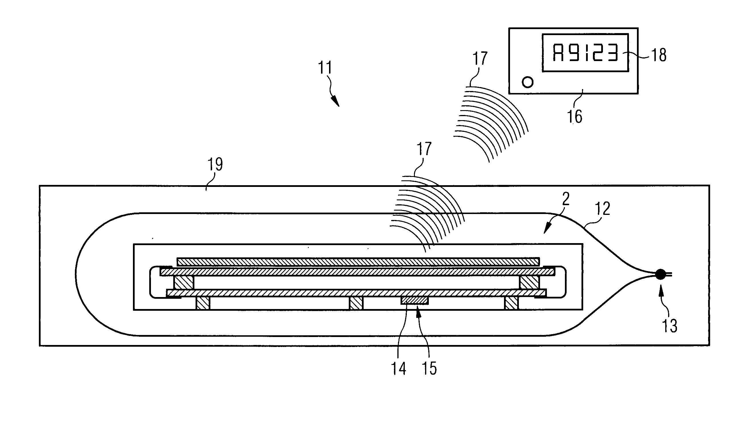
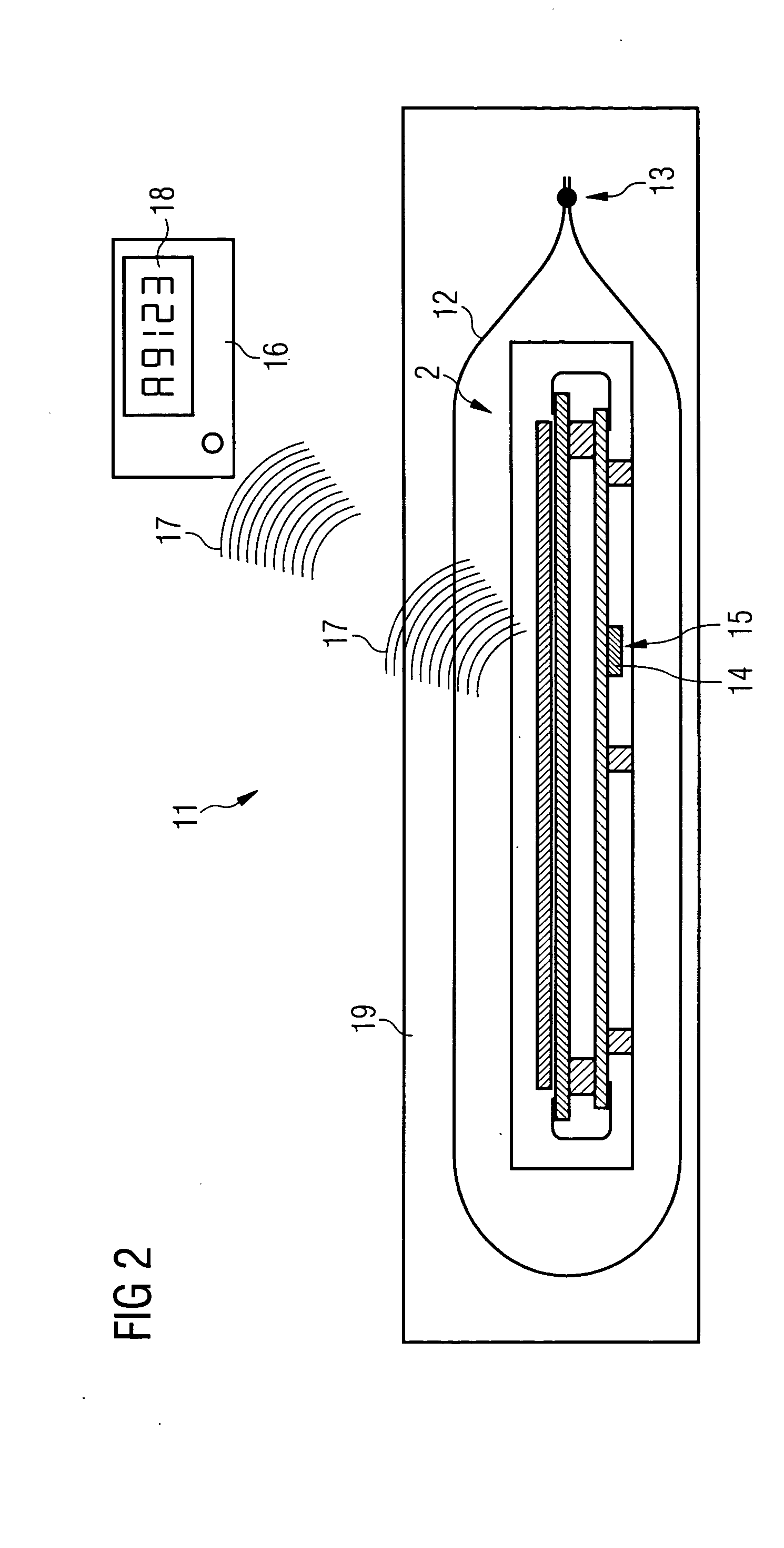
[0010] An object of the present invention is thus to create a device that can also be used in the above case as well as a corresponding method for identifying a component surrounded by an external package, especially a semiconductor X-ray detector, which removes the need to open an external package beforehand for the purposes of identifying the component contained within it.
[0013] By contrast with the identification elements already known in the prior art in the form of transponders, secure identification of the component through the external package is possible using the inventive method even if the external packaging of the component does not allow electromagnetic radiation to pass through. Thus the method can be used without any problems for the purposes mentioned at the beginning of this document for fast identification of a semiconductor X ray detectors.
[0015] Preferably component information to identify the component is stored in the identification element. The component information can for example be the generic variant, the series and / or the type of the component. Preferably the component information however contains data for complete identification of the component, for example a consecutive serial or production number etc. This ensures a secure, unique identification of the component.
[0016] Advantageously the device features a readout device and the identification element is embodied such that the component information can be transmitted by means of the acoustic methods or the scanning method from the identification element to the read-out device and can then for example be displayed using a display device. This embodiment means that the component information on the component itself does not absolutely have to be a available in a form which can be read and understood directly by a human being. Furthermore the information density on the information element can be increased compared to directly discemable types of representation. Further this embodiment guarantees that only authorized personnel who are in possession of the readout device can undertake identification of the component. In addition this embodiment allows integration of the inventive device into automatic manufacturing, packaging and dispatch sequences.
[0018] A further advantageous embodiment of the invention makes provision for the component information to be discerned by a user, e.g. a checker, by scanning and / or directly by listening through the external package. This embodiment makes possible an especially simple and thereby low-cost manufacturing of the identification element in accordance with the invention.
[0022] It is especially preferred for the identification element to be an integral part of the component. The advantage of this is that the identification element can no longer be detached from any component and thus guarantees a secure and unique identification. The other advantage is that error sources caused by applying an identification element that is not suitable for the component involved are excluded since the element is integrated during the manufacturing process of the component into the component itself. The component and the identification element are produced at low cost in one manufacturing step. Finally this embodiment prevents attempts at manipulation which are intended to intentionally put incorrect component information on the component or to swap existing component information for other component information. Thus the identification element is at the same time a seal of quality and origin for the component equipped with it.

Problems solved by technology

However these systems generally only function under some circumstances or in many cases not at all if the object to be identified or the transponder arranged on it or in it is itself surrounded by a metalized packaging through which electromagnetic radiation cannot pass.

Method used


Image

  • Device and method for identifying a component surrounded by an outer package
  • Device and method for identifying a component surrounded by an outer package
  • Device and method for identifying a component surrounded by an outer package

Examples


Embodiment Construction

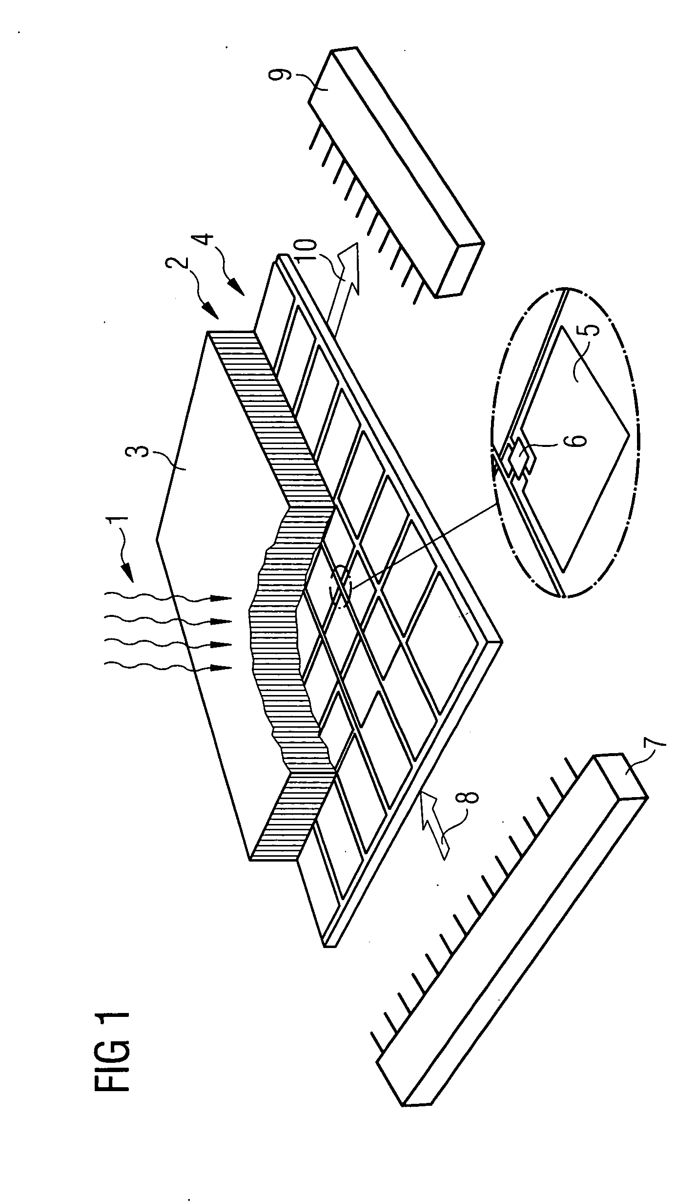
[0027]FIG. 1 shows an exemplary embodiment of a component 2 a semiconductor X-ray detector 2, on which imaging X-radiation 1 occurs.

[0028] The semiconductor X-ray detector 2 features in the direction of the X radiation 1 an image-sensitive X-ray conversion layer 3. In the X-ray conversion layer 3 the arriving X radiation 1 is converted into electromagnetic radiation at low frequency, for example light. The light is then detected by an active readout matrix 4 located immediately be hind the X-ray conversion layer 3 and converted into a latent electrical charge pattern corresponding to the X-ray image. To this end the readout matrix 4 features a number of photo diode elements 5 arranged in a matrix-shaped geometrical structure of which the electrical potential can be read out in each case via an active switching element 6—for example an integrated transistor or a diode. The electrical potential of the photo diode elements 5 is in this case proportional to the intensity of the X radia...


PUM


Abstract

Device and method for identification of a component surrounded by an external package A device (11) for identification of a component (2) surrounded by an external package (12, 19) is described. For this purpose an identification element (14) is arranged in the area of the component (2). The identification element (14) can be identified through the external package by means of an acoustic method and / or scanning method. Furthermore a method for identifying a component (2) surrounded by an external package (12, 19) using the device in accordance with the invention (11) is described.

Description

CROSS REFERENCE TO RELATED APPLICATIONS [0001] This application claims priority to the German application No. 10343497.6, filed Sep. 19, 2003 and which is incorporated by reference herein in its entirety. FIELD OF INVENTION [0002] The invention relates to a device for identification of a component surrounded by an external package, especially a semiconductor X-ray detector. In addition the invention relates to a method of identifying a component surrounded by an external package. BACKGROUND OF INVENTION [0003] For many years digital X-ray detectors have been changing classical radiography. The wide variety of newer technologies which have been in use for a long time or are becoming mature enough to be marketed include image enhancement camera systems based of television or CCD cameras, memory foil systems with integrated or external read-out unit, systems with optical coupling of the converter foil to CCDs or CMOS chips, selenium-based detectors with electrostatic readout as well as...

Claims


Application Information

Patent Timeline
Patent Type & Authority Applications(United States)
IPC IPC(8): G01T1/20G01V15/00H01L21/00H01L23/544H01L27/146
CPCG01T1/2018G01V15/00H01L27/14658H01L23/544H01L21/67294H01L2924/0002H01L2924/00
Inventor SPAHN, MARTIN
Owner SIEMENS HEALTHCARE GMBH
Learn More