
Distributed software architecture for implementing BGP

Inactive Publication Date: 2005-04-07
CISCO TECH INC
View PDF13 Cites 96 Cited by
  • Summary
  • Abstract
  • Description
  • Claims
  • Application Information

AI Technical Summary

Benefits of technology

[0017] A secondary advantage of the invention is improved fault-tolerance. If a particular processor running a BGP speaker in the router fails, only the routing peers assigned to that speaker are affected. If the failing processor is running the bRIB process, no peers are affected and the router can recover simply by having each speaker resend all of its paths to the bRIB when it restarts. In the absence of the inventive distributed architecture, a failure to the processor running the concentrated BGP implementation would affect all peers of that implementation.

Problems solved by technology

Since management of a large system of interconnected computer networks can prove burdensome, smaller groups of computer networks may be maintained as routing domains or autonomous systems.
However, the amount of processing time (i.e., bandwidth) available on the single CPU is finite which, in turn, results in limitations on the number of routes the BGP implementations can handle and limitations on the number of peers / adjacencies that the BGP implementations can support.
The amount of memory the BGP router can support is important because secondary storage, such as disks, cannot be efficiently used to store update messages given the substantial read / write latencies involved with accessing the disks.
As a result, CPU, memory and even communication scaling becomes an issue with the BGP implementation.
Such a multi-processor implementation has a fundamental limitation that, from the point of view of a peer, each processor resembles a separate router.
The multiple-router model is operationally more complex than a single router; that is, it is easier and more cost effective, from an operational cost point of view, to operate a single router than it is to configure a plurality of routers to interoperate.

Method used


Image

  • Distributed software architecture for implementing BGP
  • Distributed software architecture for implementing BGP
  • Distributed software architecture for implementing BGP

Examples


Embodiment Construction

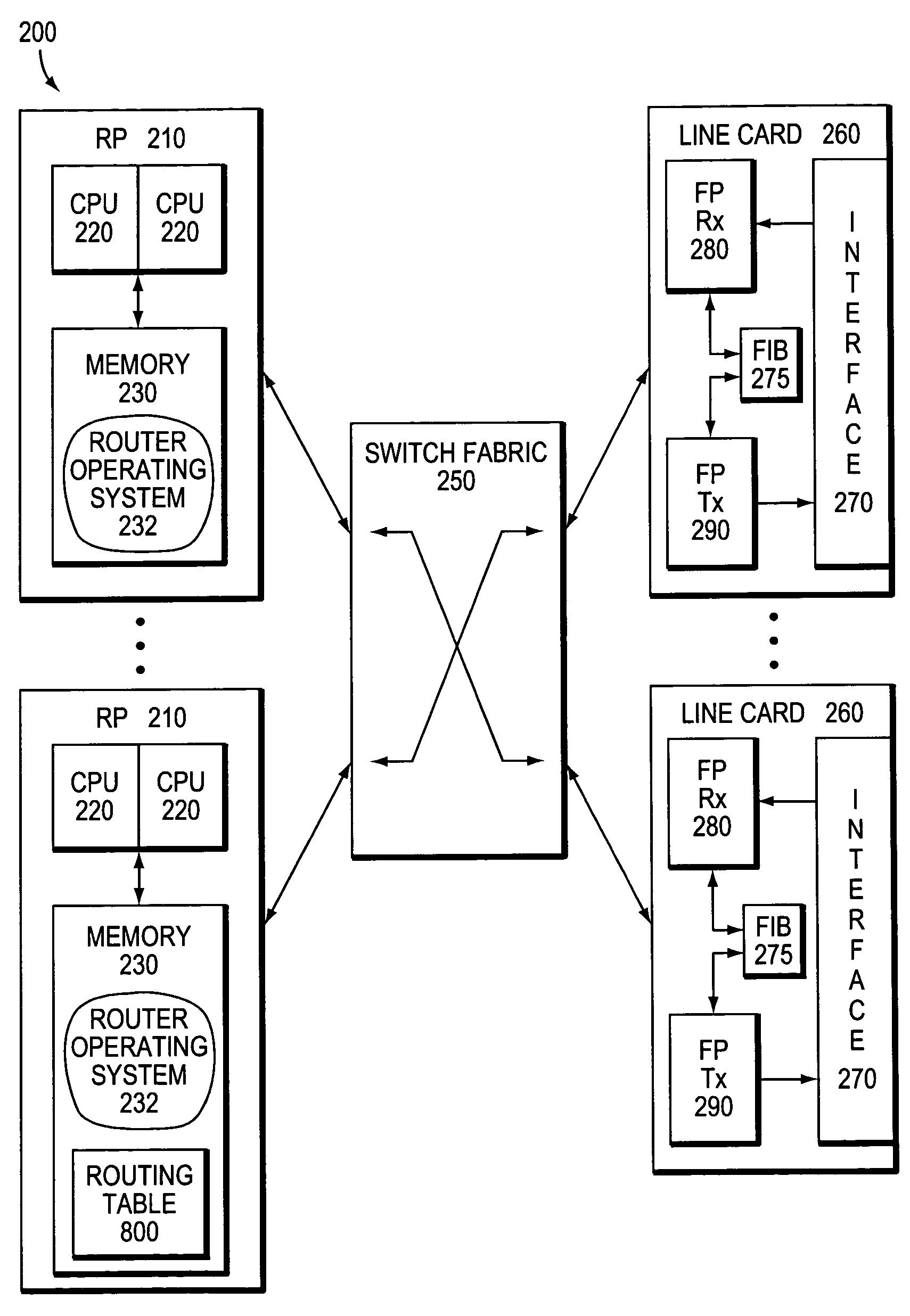
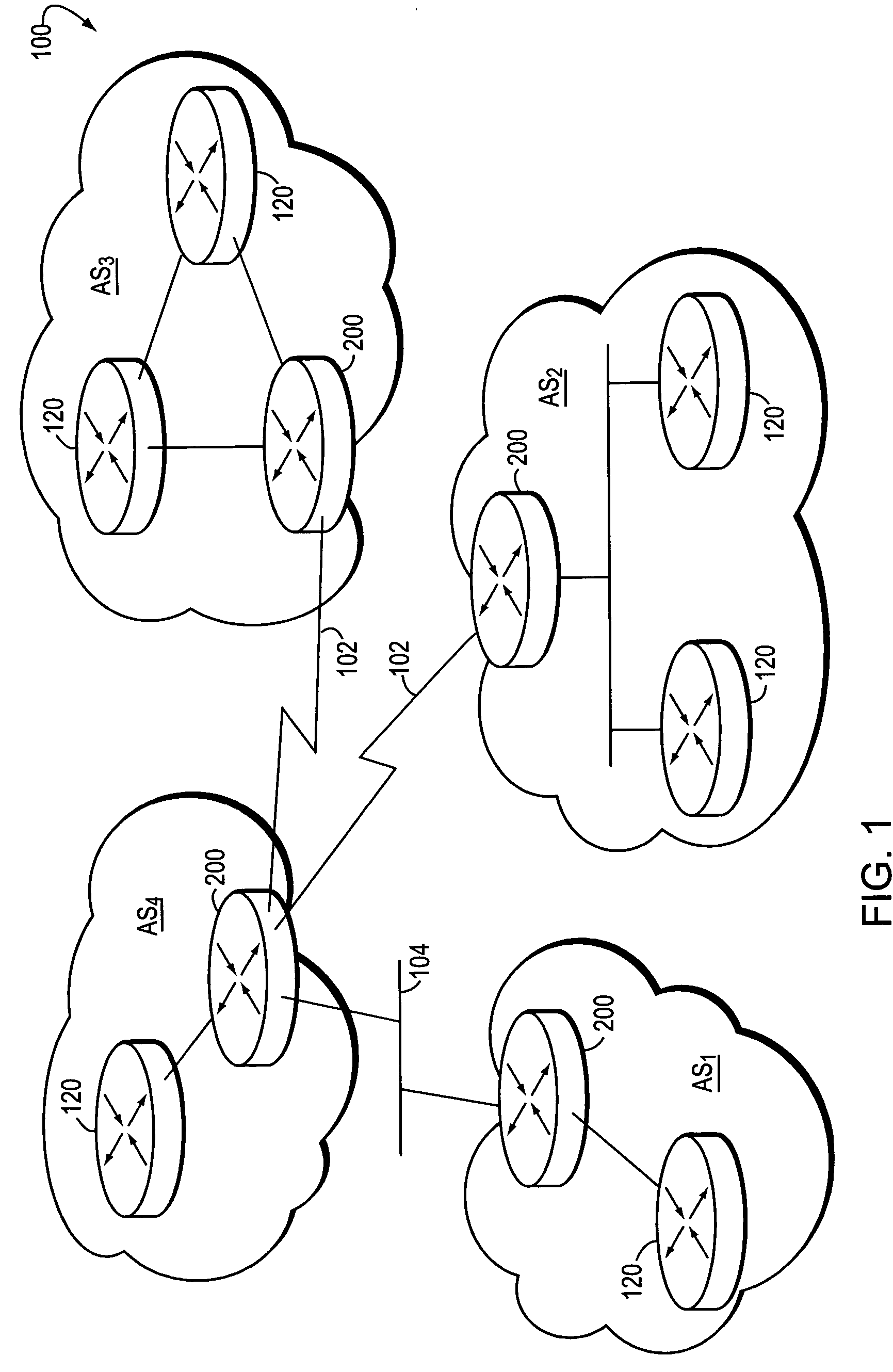
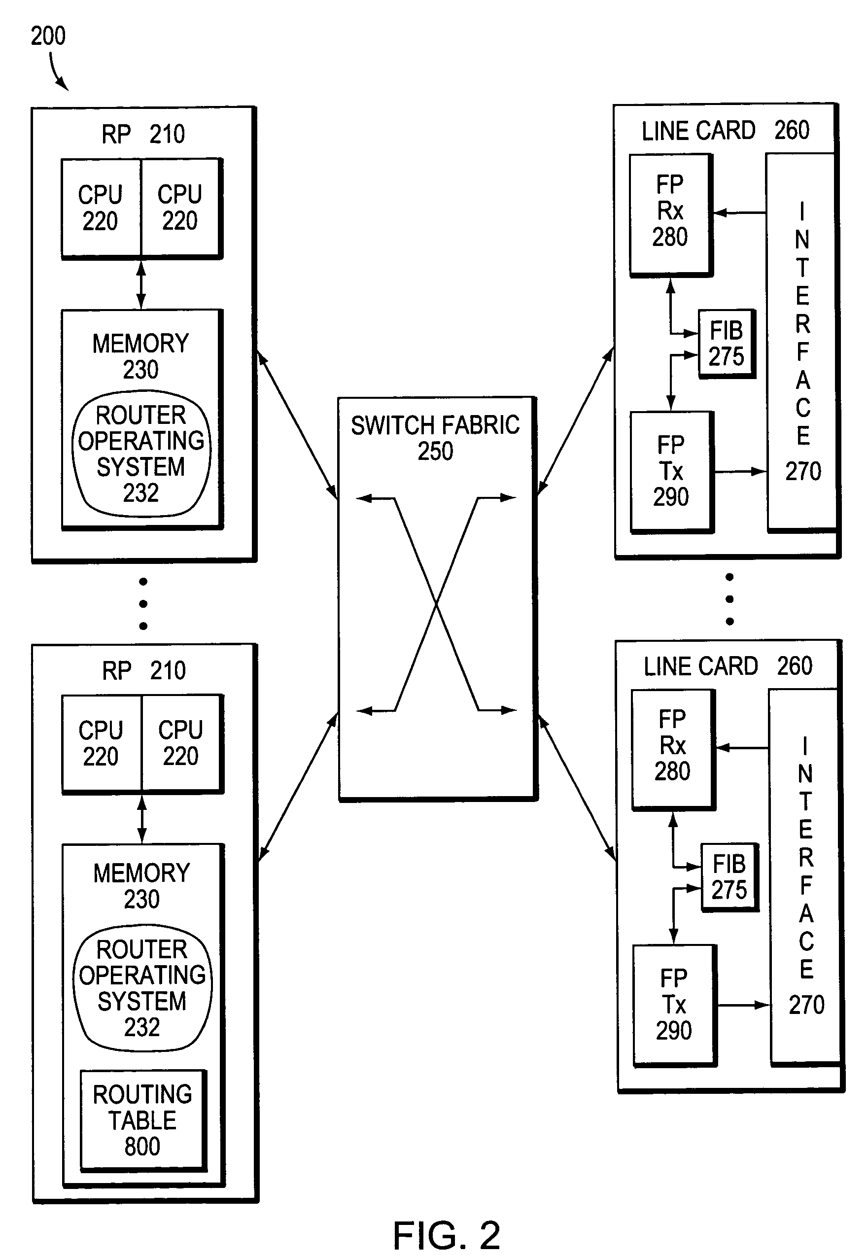
[0029]FIG. 1 is a schematic block diagram of a computer network 100 comprising a plurality of routing domains or autonomous systems interconnected by intermediate nodes, such as conventional intradomain routers 120 and interdomain routers 200. The autonomous systems may include various routing domains (AS1-4) interconnected by the interdomain routers. The interdomain routers 200 are further interconnected by shared medium networks, such as local area networks (LANs) 104, and point-to-point links 102, such as frame relay links, asynchronous transfer mode links or other serial links. Communication among the routers is typically effected by exchanging discrete data packets or messages in accordance with pre-defined protocols, such as the Transmission Control Protocol / Internet Protocol (TCP / IP). It will be understood to those skilled in the art that other protocols, such as the Internet Packet Exchange (IPX) protocol, may be advantageously used with the present invention.

[0030]FIG. 2 i...


PUM


Abstract

A distributed software architecture implements a routing protocol as a set of processes running on a set of processors of a router. The distributed processes cooperate in a manner that internally exploits the distributed set of processors, yet externally presents an appearance / behavior of a single routing protocol process communicating with its peers in the network. The distributed nature of the architecture is achieved without altering the fundamental routing protocol, but by apportioning certain functions / tasks of the protocol among various processes in the multiprocessor router.

Description

FIELD OF THE INVENTION [0001] The invention relates generally to routing protocols used in computer networks and, more particularly, to an efficient and scalable implementation of a routing protocol. BACKGROUND OF THE INVENTION [0002] A computer network is a geographically distributed collection of interconnected communication links used to transport data between nodes, such as computers. Many types of computer networks are available, with the types ranging from local area networks (LANs) to wide area networks (WANs). The nodes typically communicate by exchanging discrete packets or messages of data according to pre-defined protocols. In this context, a protocol consists of a set of rules defining how the nodes interact with each other. [0003] Computer networks may be further interconnected by an intermediate node, such as a router, to extend the effective “size” of each network. Since management of a large system of interconnected computer networks can prove burdensome, smaller gro...

Claims


Application Information

Patent Timeline
IPC IPC(8): H04L12/56
CPCH04L45/04
Inventor BALL, DAVID ALEXANDERBENNETT, R. ERICHESKETH, MARTINSCUDDER, JOHN GALENWARD, DAVID D.
Owner CISCO TECH INC
Learn More