Eureka AIR delivers breakthrough ideas for toughest innovation challenges, trusted by R&D personnel around the world.

Acoustic particulates density sensor

Inactive Publication Date: 2005-04-14
WAYNE STATE UNIV
View PDF27 Cites 6 Cited by
  • Summary
  • Abstract
  • Description
  • Claims
  • Application Information

AI Technical Summary

Benefits of technology

[0007] The present invention monitors the change in the speed of sound in the gas being tested. Since the speed of sound is intimately related to the composites of the air mixture and since the speed of sound of clean air at any temperature and humidity can be calculated exactly, it is possible to estimate the density of any foreign particulates in the air by observing changes in the speed of sound. Formulations are derived that correlate the change in the speed of sound of the air mixture to their density fluctuations, thus allowing people to estimate the mass density of foreign particulates under any temperature and humidity. This new technique may include a function generator, power amplifier, speaker, humidity meter, thermometer, microphones, oscilloscope, and personal computer that are readily available in the market.

Problems solved by technology

The disadvantage of this new technique is that it cannot estimate the sizes of these foreign particulates.
On the other hand, the conventional methodology described above cannot measure the sizes of the particulates either.

Method used


Image

  • Acoustic particulates density sensor
  • Acoustic particulates density sensor
  • Acoustic particulates density sensor

Examples


Embodiment Construction

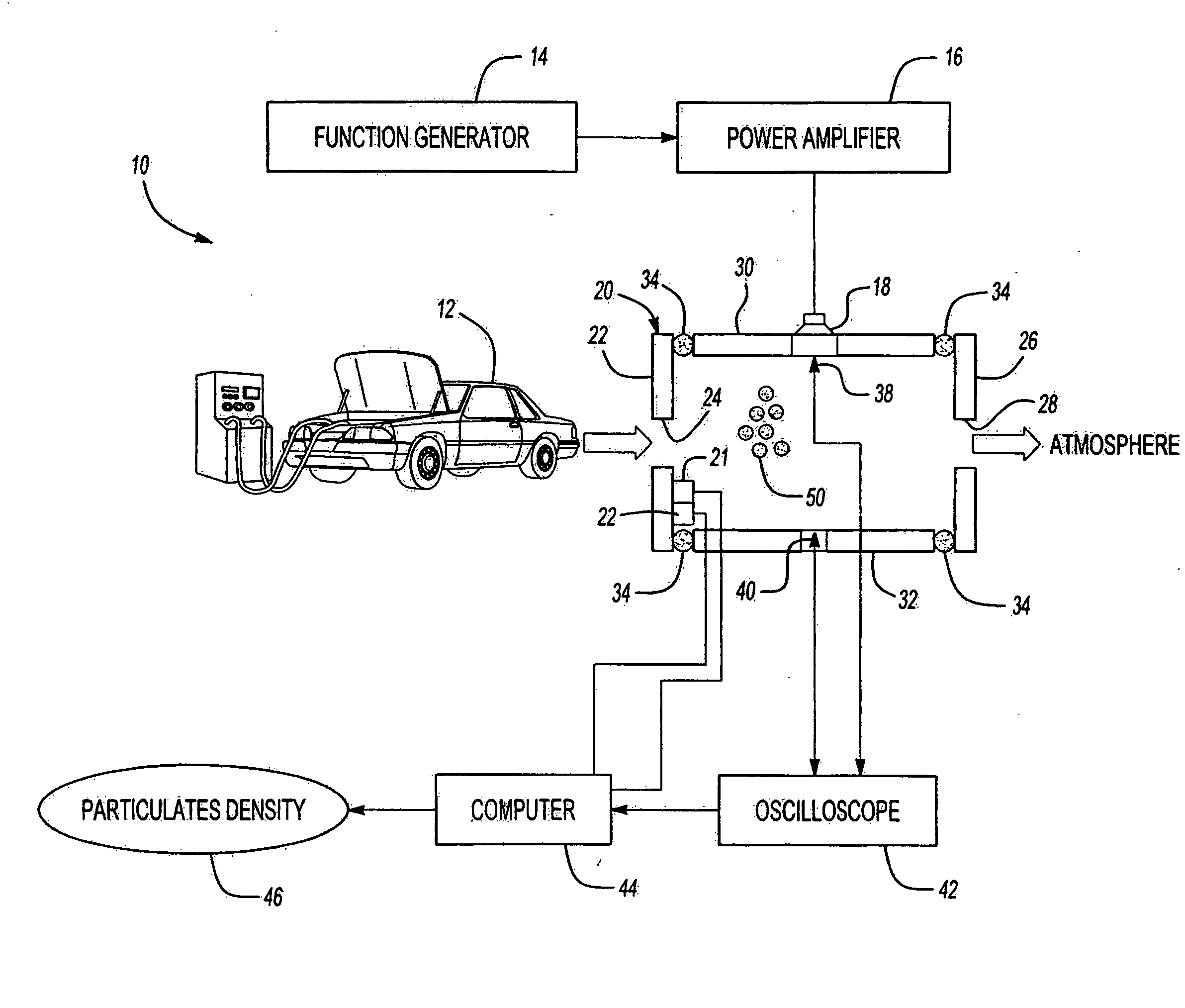
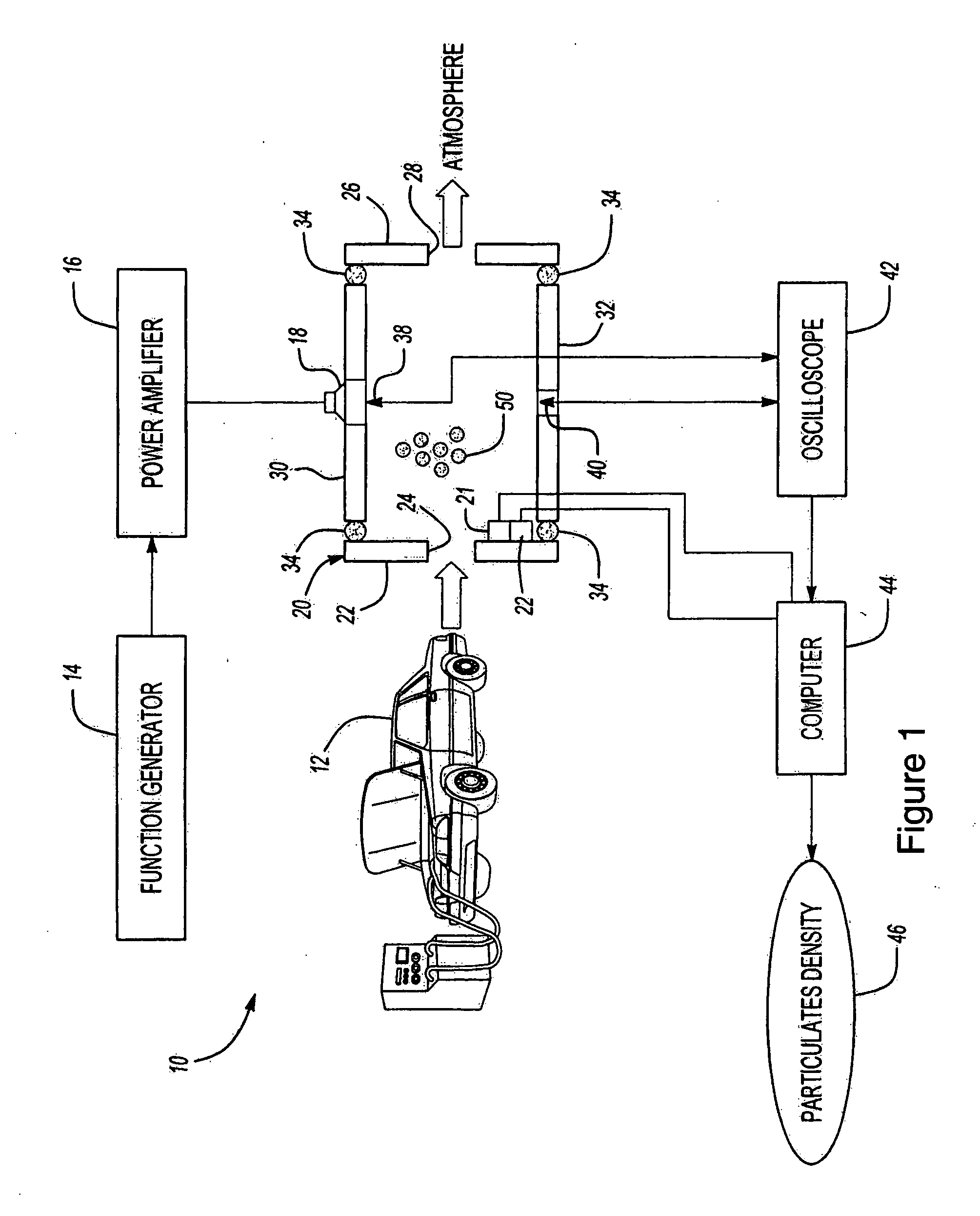
[0013]FIG. 1 schematically illustrates the acoustic particulates density sensor 10 of the present invention in one potential use in measuring the particulate density of exhaust from a vehicle 12. The sensor 10 includes a function generator 14 which sends out an impulse that is amplified by a power amplifier 16. This impulse is emitted through a loudspeaker 18 mounted over an opening on a tube 20. An exhaust system of the vehicle 12 discharges a gas mixture through the tube 20 to atmosphere. A thermometer 21 and a humidity meter 22 measure the temperature and relative humidity of the airflow inside tube 20.

[0014] The tube 20 comprises a forward wall 22 having an opening 24 for receiving the exhaust gases and an opposing rearward wall 26 having an opening 28 for discharging the exhaust gases to atmosphere. The tube 20 further includes sidewalls 30 and 32 enclosing the tube 20 and connecting forward wall 22 to rearward wall 24. Foam 34 is disposed between the sidewalls 30, 32 and the ...


PUM


Abstract

A technique for determining particulate density in a fluid monitors the changes in the speed of sound. Since the speed of sound is intimately related to the composites of the air mixture and since the speed of sound of clean air at any temperature and humidity can be calculated exactly, it is possible to estimate the density of any foreign particulates in the air by observing changes in the speed of sound. Formulations are derived that correlate the change in the speed of sound of the air mixture to their density fluctuations, thus allowing people to estimate the mass density of foreign particulates under any temperature and humidity. Alternatively, the change in density of the air mixture can be detected, thereby indicating the presence of contaminants and a possible alarm, even if the contaminants are not yet identified.

Description

RELATED APPLICATIONS [0001] This application is a continuation-in-part of U.S. Ser. No. 10 / 308,868, filed Dec. 2, 2002, which claims priority to U.S. Provisional Ser. No. 60 / 338,409 filed Dec. 5, 2001.BACKGROUND OF THE INVENTION [0002] This invention provides a cost-effective methodology to measure the mass concentration of impurities in the air resulting from the exhaust of a combustion system such as diesel and gasoline engines used in the automotive industry. This methodology can also be used to measure any particulates in gas streams used in industry. It is drastically different from the conventional methods that are currently used by the automotive companies in monitoring particulates emissions. The invention can also be used to detect and / or identify and / or measure pollutants in ambient air.[0003] Test data have shown that the average sizes of particulates from the exhaust of combustion systems are in the order of nanometers, or 10−9 meter, which are invisible but can be harmf...

Claims


Application Information

Patent Timeline
IPC IPC(8): G01N1/22G01N15/06G01N29/024G01N29/30
CPCG01N1/2202G01N1/2252G01N15/06G01N29/024G01N2291/02845G01N2001/2223G01N2291/011G01N2291/0217G01N2291/02818G01N29/30
Inventor WU, SEAN F.BENIWAL, RAVINDER S.
Owner WAYNE STATE UNIV
Why Eureka
Eureka Blog
Learn More