Article feeder

a feeder and article technology, applied in the field of article feeders, can solve the problems of increasing the complexity of the feeder, requiring each substitution requires laborious and time-consuming clearing, so as to enhance the proclivity for articles and shorten the slide distance

Inactive Publication Date: 2005-04-14
KVAL
View PDF19 Cites 21 Cited by
  • Summary
  • Abstract
  • Description
  • Claims
  • Application Information

AI Technical Summary

Benefits of technology

[0009] An enclosure is desirably provided about the collator section floor for normally retaining the desired collection of random articles from falling out of the collator section floor as it oscillates, preferably including a wall along the upstream end of the floor. The enclosure desirably contains a gate closure at the upstream end of the floor that may be opened in order to allow the articles to drop from the device during changeover when the operator is preparing to feed a different screw or other workpiece with the device.
[0010] Other features of the invention apply particularly to feeders having a collator that transfers collated articles to a separate dispensing section which is normally inclined downwardly from point of transfer from the collator section so that the transferred articles can slide down to an escapement for dispensing. In one such feature, selectively removable detents are provided for the collator section slots at a location intermediate the upstream and downstream ends of the floor. When in place in the slots, the detents will stop articles that are queued in the slots downstream of their location from moving to the upstr

Problems solved by technology

A problem with foregoing type of feeder is the tendency of the random articles in the receptacle to cause jams that impede the movement of the queued articles in the first set of slots over to the second slots since the random articles sliding in the box reach the entrances to the second set of slots about the same time as those sliding down in a queue in the first set of slots.
However this increases the complexity of the feeder and the rand

Method used


Image

  • Article feeder
  • Article feeder
  • Article feeder

Examples


Embodiment Construction

[0023] The following description illustrates the manner in which the principles of the invention are applied but is not to be construed as limiting the scope of the invention.

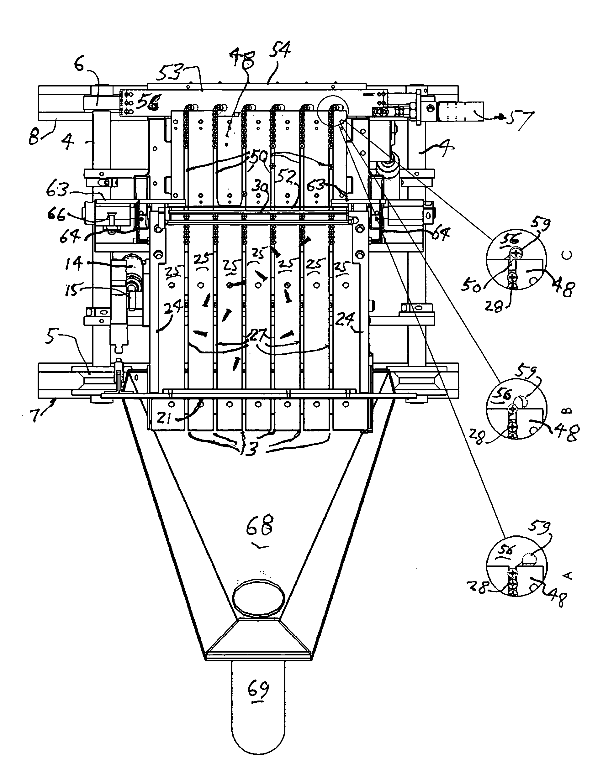
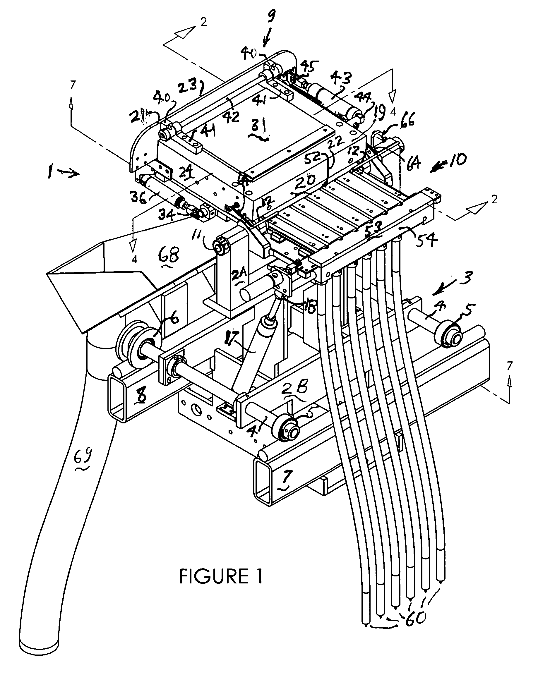
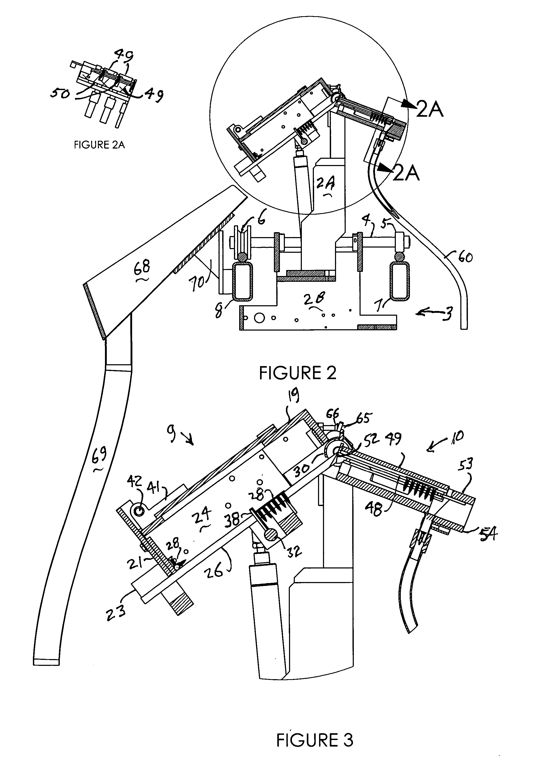
[0024] The article feeders of this invention are intended for feeding screws and other workpieces individually to receivers usually for application of the screws in a fastening operation by automatic screw driving equipment. For this purpose they may be mounted for operation at a stationary site or on a carriage or the like for movement together with screw driving equipment to screw driving locations. In the embodiment described here, the screw feeder is mounted on a carriage for use with associated machinery for applying hinges to doors and door jambs, such as described in my U.S. Pat. No. 6,398,004. The carriage moves on rails to appropriate locations along with automatic screwdrivers, to which it supplies screws for automatically applying hinges at those locations.

[0025] Referring to the drawings, particul...


PUM


Abstract

A screw feeder adapted for rapid changeover of the type of screws to be fed. The feeder has a collator section having a floor with slots to collate random screws into rows and an enclosure about the floor for retaining random screws on the floor. The collated screws are fed along the slots into slots in a dispensing section of the feeder where they are then moved in queues to an escapement to be picked off one by one for deposit into a receiver. The collator section floor is oscillated about an axis between a position where the floor slopes downward from a downstream end in the slot direction from an upstream end in the opposed slot direction to a position where the floor slots slope upward to the upstream end. The collator section enclosure has a gate closure at the upstream end of the floor and the slots on the floor extend completely to the upstream end so that, with the gate open and the collator section oscillated to tilt the slots downward toward the upstream end, the screws in the slots will slide to the upstream end and out of the feeder to empty it. A chute is provided below the upstream end to collect the screws falling from the feeder. The screw feeder may have a collator section that collates and feeds screws along slots to the slots of a separate dispenser section for dispensing. For emptying the feeder for screw changeover, the dispensing section is raised so that the screws slide back to the collator section held at the lower position for screw removal. A flow regulator gate adjacent the dispenser section is openable on rotation downward of the collator section to clear screw jambs. The regulator gate also opens when the dispensing section is raised to clear the screws back to collator section for changeover. Detents are provided in the collator section slots at an intermediate location therealong to maintain the collated screws closer to dispensing section for ease of transfer thereto. The detents are selectively removable so that they will not interfere with emptying the feeder on changeover to new screws.

Description

BACKGROUND OF THE INVENTION [0001] This invention relates to devices for collating and feeding screws, nails and other work articles of the same or similar configuration. Such feeders are utilized for supplying such articles to work stations where the articles may be further collated, transported or packaged or they may be used to carry out various operations such as fastening workpieces together, e.g. fastening hinges to door jambs. [0002] Conventional feeders of screws, nails and other uniform articles include devices such as those described in U.S. Pat. Nos. 2,943,764, 3,071,291 and 4,222,495 which collate articles lying randomly in a receptacle by intercepting the articles with a collating device having one or more channels or slots into which the articles drop and which thus capture the articles in queued fashion. The articles are slidable within the slots so that when the slots are tilted above the horizontal about a pivot point at one end thereof, the queued articles will sli...

Claims


Application Information

Patent Timeline
IPC IPC(8): B23P19/00B65G47/14
CPCB23P19/002B65G47/1414B23P19/003
Inventor KVALHEIM, ANDREW M.
Owner KVAL
Why Eureka
Try Eureka