
Variable length packet communication device

a packet communication and variable length technology, applied in the field of routers, can solve problems such as reducing the throughput of the switch, and achieve the effects of less overhead in the switch, less hardware on the transmitting interface side, and less load on the scheduler of the switch

Inactive Publication Date: 2005-04-14
HITACHI LTD +1
View PDF8 Cites 16 Cited by
  • Summary
  • Abstract
  • Description
  • Claims
  • Application Information

AI Technical Summary

Benefits of technology

[0010] In the technique, however, each of the small packets has a field for indicating its destination. There is more overhead because the field occupies relatively large part of the small packet. This decreases the throughput of the switch.
[0012] An object of this invention is providing a router that the throughput of the switch is high and the amount of hardware is small.
[0014] Another object of this invention is providing a router that can perform parallel processing in switch effectively.
[0016] In the present invention, switch is reserved in packet units. That is, when an input interface starts to transmit cells generated from a packet to its destination output interface through the switch, the switch is reserved until all the cells arrive at the output interfaces. In other words, the output interface does not receive any cell from another input interfaces until all the cells arrive at the output. However, the switch may transmit a packet to be transmitted to an output interface different from the output interface. In such way, the variable length communication device reassembles the cells into the packet by queuing the cells in arrival order at the output interface. And, in the present invention, due to adding the field for indicating the output route to only the head cell, there is less overhead in switch and less the amount of hardware in transmitting interface side. Moreover, in this invention, since a switch on / off operation itself is performed cell by cell, there is less load of scheduler of the switch.
[0017] In the another present invention, a packet container containing a packet / packets is provided. An input interface has a plurality of queues, each of which corresponds to each of the output interfaces respectively. The input interface stores packets into the their respective queues and stuffs a packet / packets to be transmitted to the same output interface into the same container in such a manner as a packet does not extend over two containers. The switch performs switching by the containers. The output interface takes the packet / the packets from the container and transmits the packet to the transmission path. This facilitates reassembling a packet at the output interface. Moreover, using the container facilitates large capacity of the switch, since unit of switching and the number of parallel processing bits increase.
[0018] Moreover, in the another present invention, a fixed length container is provided. An input interface permits a packet to extend over a plurality of containers. An input interface has a plurality of queues, each of which corresponds to each of the output interfaces respectively. The input interface stores packets into their respective queues and stuffs a packet / packets to be transmitted to the same output interface into the same container. At the time, a packet may extend over two containers. The switch performs switching in container units. The output interface takes the packet / the packets from the container and transmits the packet to the transmission path. In this case, the output interface has packet reassembling buffers that correspond to input interfaces respectively in order to reassemble the packet that extends over two containers. This facilitates large capacity of the switch. Moreover, since packets are stuffed into a container without consideration the end of each packet and without a PAD, efficiency of the switch is promoted.

Problems solved by technology

This decreases the throughput of the switch.

Method used


Image

  • Variable length packet communication device
  • Variable length packet communication device
  • Variable length packet communication device

Examples


third embodiment

[0041] We explain a packet communication device of a first, second and third embodiment of the present invention.

[0042] First of all, using FIG. 17 and FIG. 18, we explain a common block diagram for a packet communication device of a first, second and third embodiment of the present invention.

[0043] A packet communication device shown in FIG. 17 is comprising input physical layer processing unit 102, input interface 3, core switch 101, output interface 4, input physical layer processing unit 103 and controller 100. Input physical layer processing unit 102 performs terminated processing of the physical layer of an input variable length packet. Input interface 3 decides the output path of the packet. Core switch 101 transmits the packet to the desired path. Output interface 4 performs transmission processing for the packet. Input physical layer processing unit 103 performs processing of the physical layer of the packet such as putting the packet in a frame. Controller 100 performs se...

first embodiment

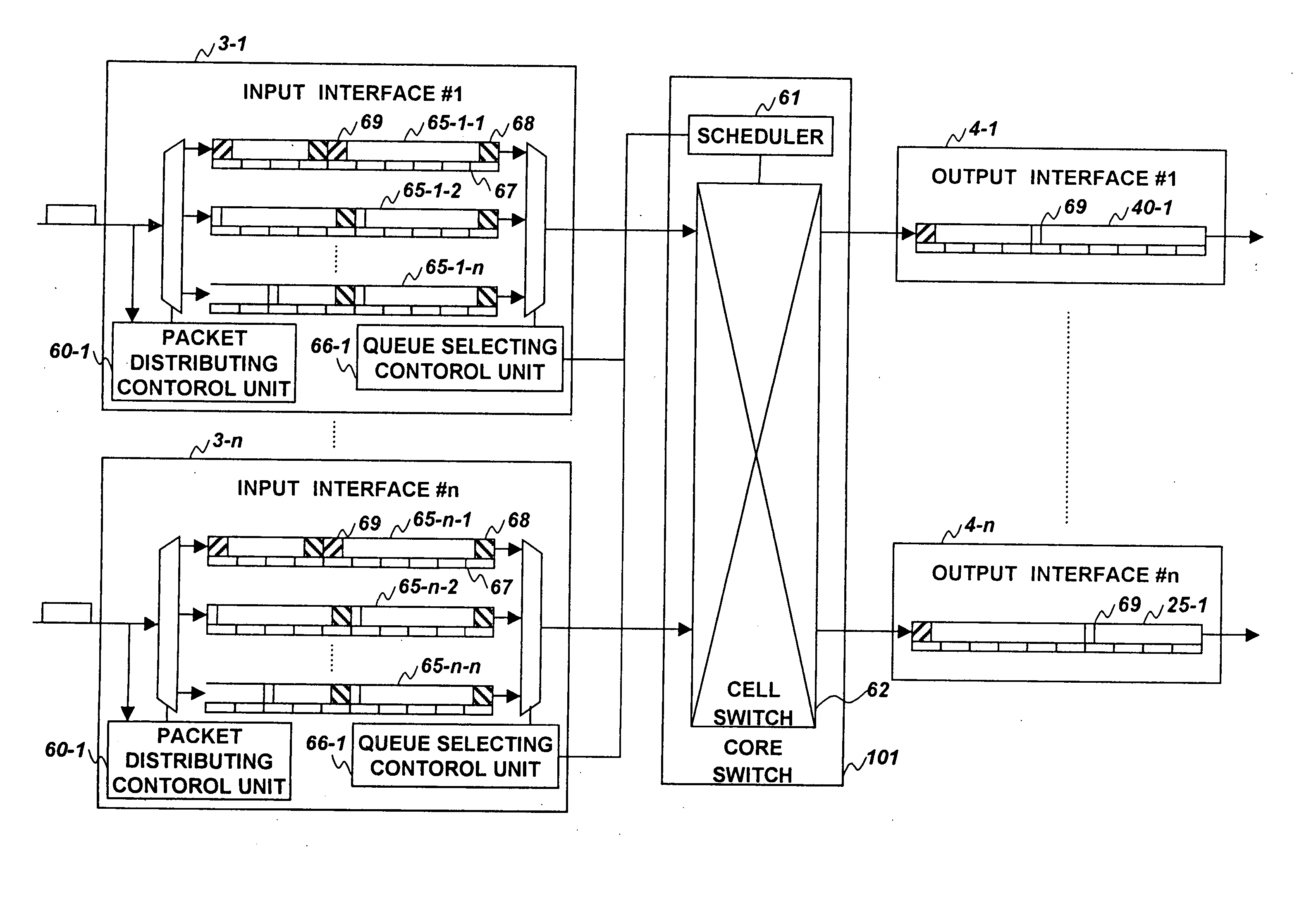
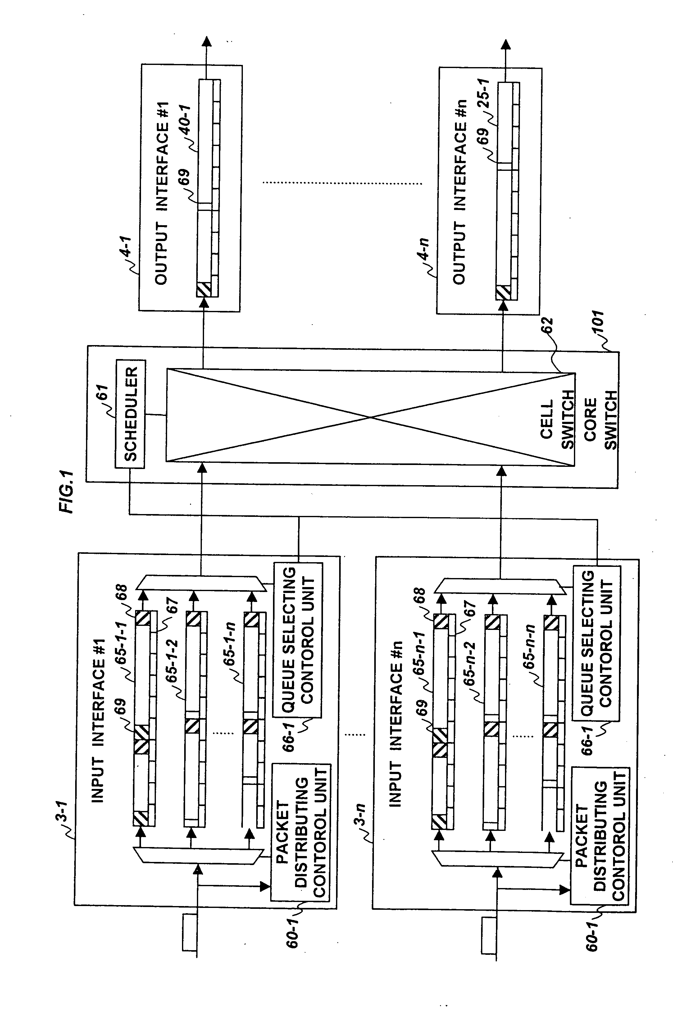
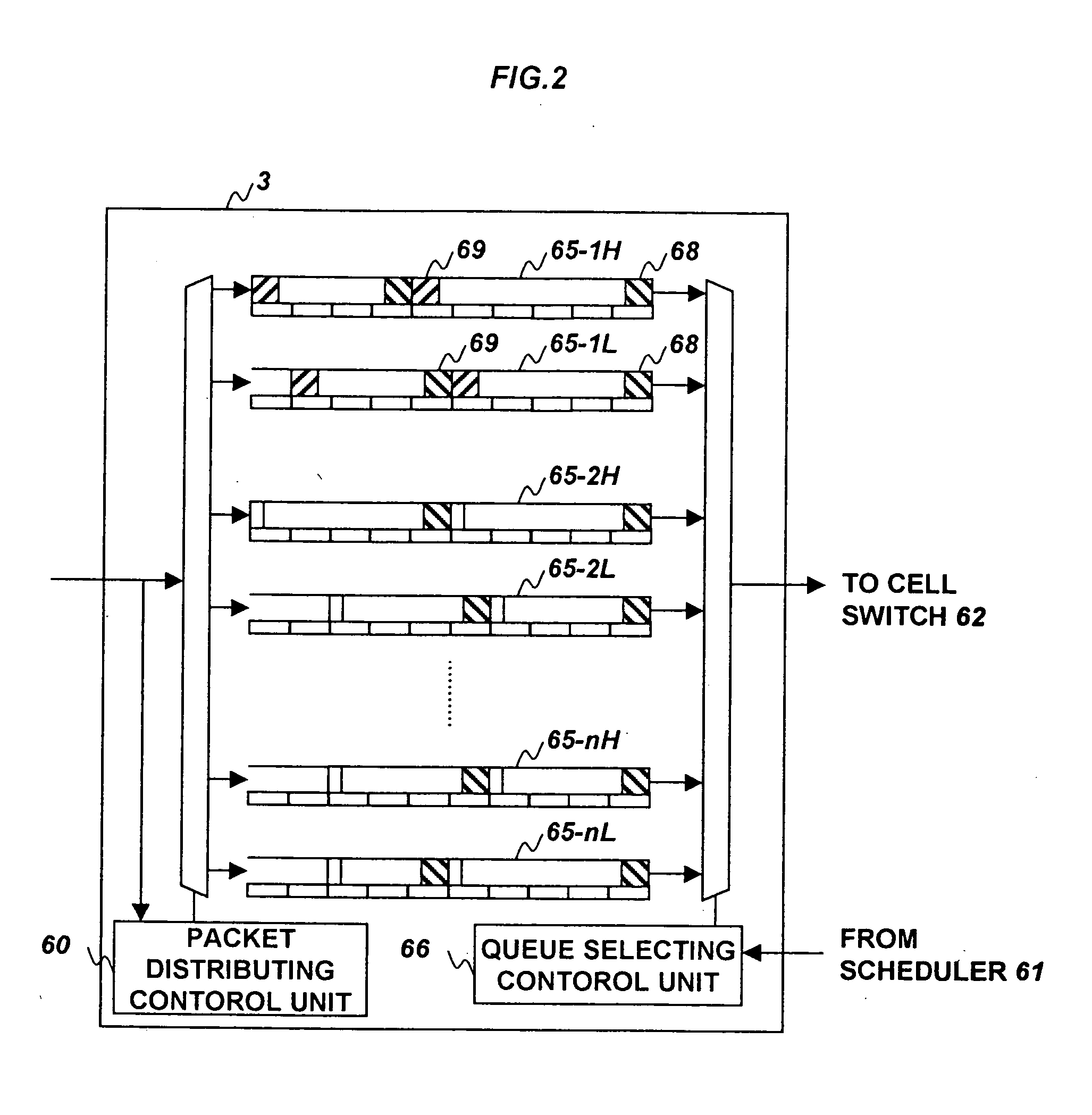
[0047]FIG. 1 is a schematic view for a packet communication device of the present invention. FIG. 1 shows input interface 3, core switch 101 and output interface 4 in detail. Cell switch 62, for example, is composed of a crossbar switch. Each of interfaces has “n” queues 65 corresponding to n output interfaces 4 respectively, packet distributing control unit 60, and queue selecting control unit 66. The number of “n” is the number of output interfaces 4. Packet distributing control unit 60 specifies the output interface 4 to which the input variable length packet is to be transmitted based on the header information of the input packet and distributes the input packet to the corresponding queue 65. Queue selecting control unit 66 selects one of the n queues 65 and transmits the variable length packet queued in it to cell switch 62. Each of output interfaces 4 has a queue 40. Hereinafter, a variable length packet may be called a packet.

[0048] One of the futures of a communication devic...

second embodiment

[0071]FIG. 3 is a schematic view for a packet communication device of the present invention. In this embodiment, input interfaces 3 generates a container to be put a packet / packets to be transmitted to the same output interface 4. Container switch 2 in core switch 101 performs switching in container units. Container switch 2 reserves / releases the switch resource by a time slot, which is the time a container is through container switch 2. Output interface 4 retrieves the packet / the packets from the container and transmits the packet / the packets to the transmission line connected to output interface 4.

[0072] Each of input interfaces 3 has “n” queues 15 corresponding to output interfaces 4 respectively and packet distributing control unit 10 that distributes a input packet to queue 15 based on its destination. Herein, the number of “n” is the number of output interfaces 4. The upper section of each of queues 15 shows packets and the lower section of each of the queues shows container...


PUM


Abstract

An input interface segments a variable length packet into plurality of fixed length cells and generates an internal switching information based on the header information of the variable length packet. The input interface transmits the information to a switch and, after that, transmits the cells as the following cells of the information to the switch. The switch performs switching processing to the succeeding cells based on the information. Therefore, the information is not added to the cells. When an input interface starts to transmit cells generated from a packet to its destination output interface through the switch, the switch is reserved until all the cells arrive at the output interfaces.

Description

FIELD OF THE INVENTION [0001] This invention is related to a router which switches a variable length packet. BACKGROUND OF THE INVENTION [0002] By the Internet's popularization, the data traffic rapidly increases recently. In order to deal with the increase, enlargement of capacity of a communication channel, speedup and enlargement of capacity of a communication device, such as an exchange node, is important. [0003] A conventional variable length packet communication device has structure that interfaces and a microprocessor are connected to a bus. When a packet arrives at one of the interfaces, the interface transmits the packet to the microprocessor and the microprocessor analyzes the packet and transmits the packet to the desirable route. However, the bus and microprocessor are the bottleneck to perform a processing at high speed. [0004] It is also used a switching device that performs the switching in packet units, like a frame relay. The device assigns and releases switch resou...

Claims


Application Information

Patent Timeline
IPC IPC(8): H04L47/43H04L47/6275H04L47/629
CPCH04L12/5601H04L2012/5681H04L45/60H04L49/101H04L49/20H04L49/254H04L49/30H04L49/3009H04L49/3018H04L49/3027H04L49/508H04L49/608H04L2012/5651H04L2012/5652H04L45/302
Inventor SAKAMOTO, KENICHIMATSUYAMA, NOBUHITOAIMOTO, TAKESHIENDO, NOBORUWAKAYAMA, KOJIMORIWAKI, NORIHIKO
Owner HITACHI LTD
Learn More