Receiver spatial processing for eigenmode transmission in a MIMO system

a technology of eigenmode transmission and receiver, applied in the field of data communication, can solve problems such as performance degradation, and achieve the effect of improving performance and reducing cross-talk

Active Publication Date: 2005-04-14
QUALCOMM INC
View PDF12 Cites 42 Cited by
  • Summary
  • Abstract
  • Description
  • Claims
  • Application Information

AI Technical Summary

Benefits of technology

Techniques for performing receiver spatial processing in a manner to mitigate cross-talk and achieve better performance are provided herein. Initially, a transmitter and / or a receiver estimates the response of a MIMO channel and decomposes the channel response estimate to obtain steering vectors, which are estimates of the transmitter steering vectors needed to orthogonalize the NS spatial channels of the MIMO channel. The transmitter is provided with the steering vectors if they are derived by the receiver. The transmitter processes (e.g., encodes, interleaves, and modulates) NS data streams to obtain NS data symbol streams for transmission on the NS spatial channels. The transmitter performs spatial processing on the NS data symbol streams with the steering vectors to obtain NT transmit symbol streams. The transmitter then conditions and transmits the NT transmit symbol streams from the NT transmit antennas to the receiver.

Problems solved by technology

However, in a practical system, the NS spatial channels are usually not completely orthogonal to one another due to various reasons.
The cross-talk acts as additive noise that degrades performance.

Method used


Image

  • Receiver spatial processing for eigenmode transmission in a MIMO system
  • Receiver spatial processing for eigenmode transmission in a MIMO system
  • Receiver spatial processing for eigenmode transmission in a MIMO system

Examples


Embodiment Construction

The word “exemplary” is used herein to mean “serving as an example, instance, or illustration.” Any embodiment or design described herein as “exemplary” is not necessarily to be construed as preferred or advantageous over other embodiments or designs.

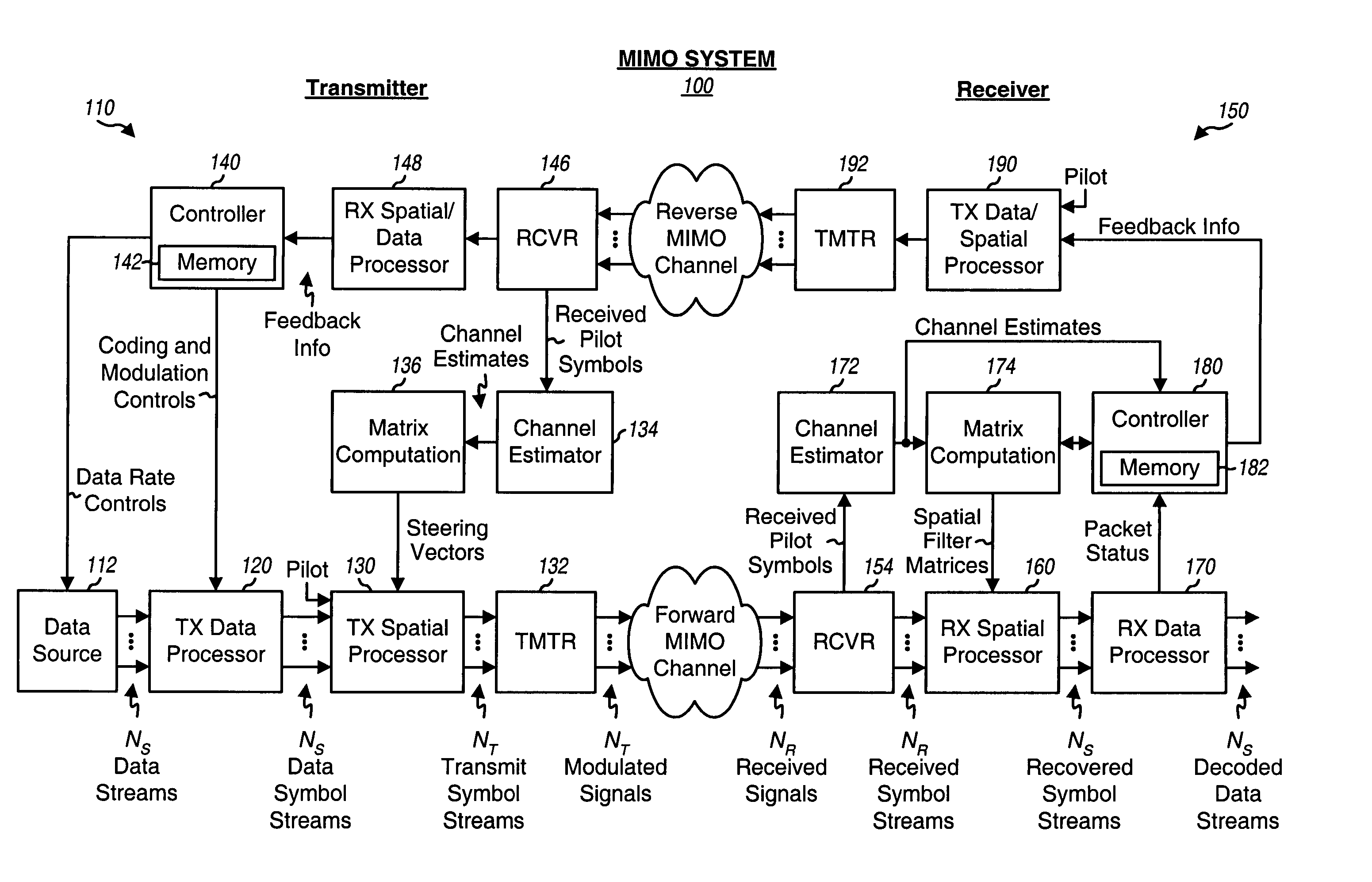
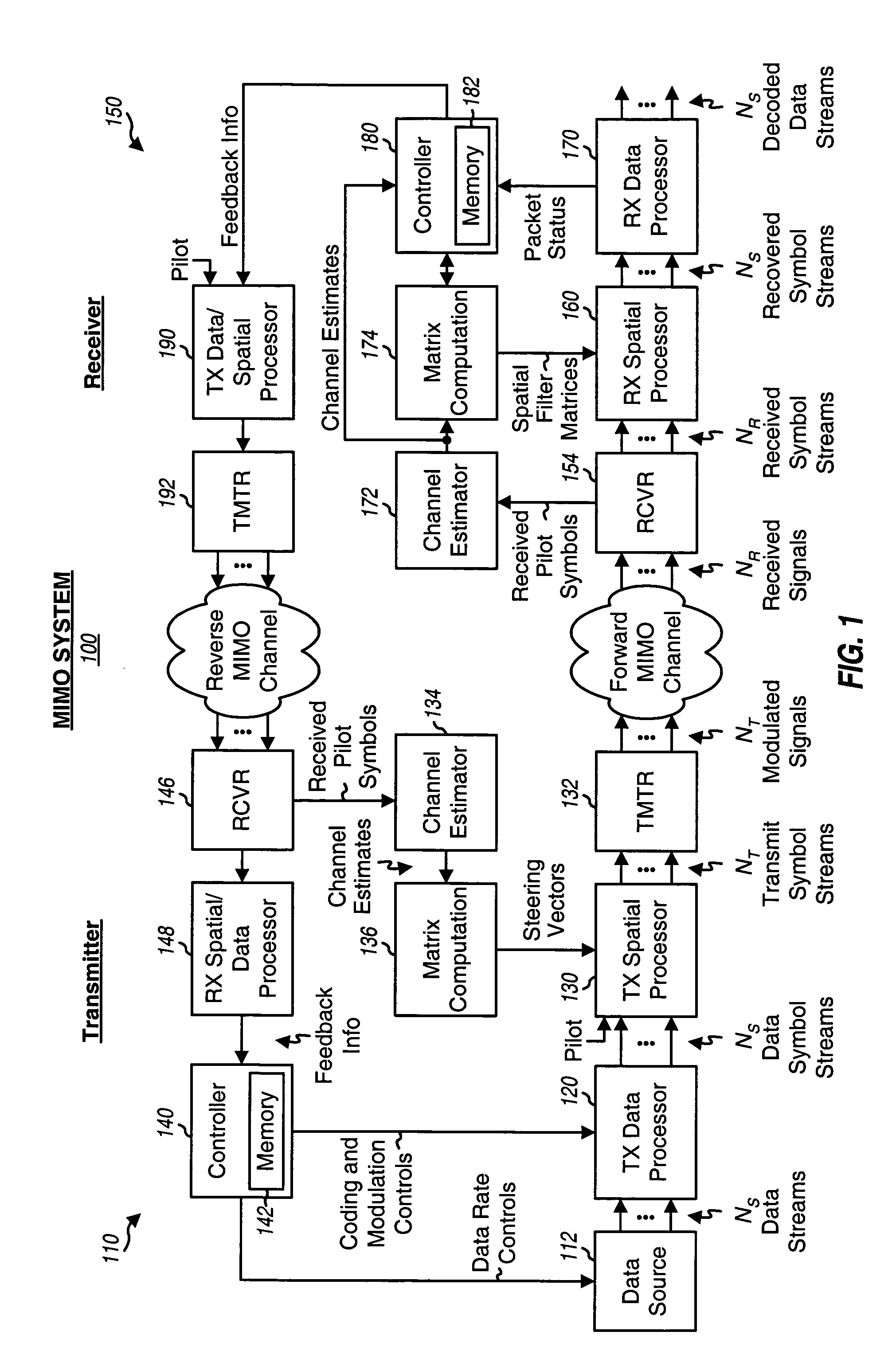
The receiver spatial processing techniques described herein may be used in a single-carrier MIMO system as well as a multi-carrier MIMO system. Multiple carriers may be provided by orthogonal frequency division multiplexing (OFDM), other multi-carrier modulation techniques, or some other constructs. OFDM effectively partitions the overall system bandwidth into multiple (NF) orthogonal subbands, which are also commonly referred to as tones, bins, or frequency channels. With OFDM, each subband is associated with a respective carrier that may be modulated with data. For clarity, the receiver spatial processing techniques are specifically described below for a MIMO system that implements OFDM (i.e., a MIMO-OFDM system).

A frequency-sele...


PUM


Abstract

For eigenmode transmission with minimum mean square error (MMSE) receiver spatial processing, a transmitter performs spatial processing on NS data symbol streams with steering vectors to transmit the streams on NS spatial channels of a MIMO channel. The steering vectors are estimates of transmitter steering vectors required to orthogonalize the spatial channels. A receiver derives a spatial filter based on an MMSE criterion and with an estimate of the MIMO channel response and the steering vectors. The receiver (1) obtains NR received symbol streams from NR receive antennas, (2) performs spatial processing on the received symbol streams with the spatial filter to obtain NS filtered symbol streams, (3) performs signal scaling on the filtered symbol streams with a scaling matrix to obtain NS recovered symbol streams, and (4) processes the NS recovered symbol streams to obtain NS decoded data streams for the NS data streams sent by the transmitter.

Description

BACKGROUND I. Field The present invention relates generally to data communication, and more specifically to techniques for performing receiver spatial processing in a multiple-input multiple-output (MIMO) communication system. II. Background A MIMO system employs multiple (NT) transmit antennas and multiple (NR) receive antennas for data transmission and is denoted as an (NT, NR) system. A MIMO channel formed by the NT transmit and NR receive antennas may be decomposed into NS spatial channels, where NS≦ min (NT, NR). The NS spatial channels may be used to transmit up to NS independent data streams to achieve greater overall throughput. Spatial processing may or may not be performed by a transmitter and is performed by a receiver in order to transmit multiple data streams on the NS spatial channels. The NS spatial channels may or may not be orthogonal to one another. Orthogonal spatial channels can only be obtained when both (1) the transmitter performs spatial processing with ...

Claims


Application Information

Patent Timeline
Patent Type & Authority Applications(United States)
IPC IPC(8): H04B7/04H04J99/00H04B7/08H04L1/06H04L25/02H04L27/26
CPCH04B7/0417H04B7/0854H04L1/0002H04L27/2601H04L1/0009H04L1/06H04L25/0206H04L1/0003H04L25/0204
Inventor KETCHUM, JOHN W.WALLACE, MARK S.WALTON, J. RODNEYHOWARD, STEVEN J.
Owner QUALCOMM INC
Why Eureka
Try Eureka