Battery connection structure, battery module, and battery pack

a battery module and connection structure technology, applied in the direction of battery/fuel cell control arrangement, cell components, propulsion by batteries/cells, etc., can solve the problems of large welding time, difficult to manufacture the entire outer diameter, large length and parallelism, and poor productivity, so as to achieve easy coupling of battery modules to each other, high precision, and stable housing

Inactive Publication Date: 2005-04-14
PANASONIC CORP
View PDF4 Cites 164 Cited by
  • Summary
  • Abstract
  • Description
  • Claims
  • Application Information

AI Technical Summary

Benefits of technology

[0018] In this connecting structure between cells, welding is performed in a stable posture in which the connection plate, that is a plain flat plate, is bridged at both sides between the ring-shaped connection-electrode portion of one of two cells arranged with their cell axis arranged in parallel and the bottom of the cell case of the other cell so as to be supported. Therefore, a trouble such as a defective joint, never occurs, thus largely improving the yield. Moreover, the number of the welding times required for jointing the connection plate and the connection-electrode portion and jointing the connection plate and the bottom of the cell case is two. Therefore, the number of the welding times is greatly reduced, thus dramatically improving the productivity. Furthermore, since the cells are arranged in parallel with their cell axis arranged in parallel, a current path between the two cells becomes the shortest because it passes through positions that are close to each other, i.e., the ring-shaped connection-electrode portion of one cell and the outer circumferential portion of the bottom of the other cell. Therefore, the electric resistance can be greatly reduced.
[0020] In this battery module, the shaping precision of the holder case made of synthetic resin, uniquely determines the dimensions of the shape. Therefore, variation in the dimensions never occurs after the battery module is assembled, thus providing the precisely-shaped battery module. Moreover, since each cell is held in a completely electrically insulated state by being accommodated in the corresponding cell-accommodating portion, the insulation ring and the outer tube made of resin in the conventional battery module are not required, reducing the cost of material and improving the productivity. Furthermore, since each cell is secured by the cover members while being in contact at four portions on its outer circumferential surface with four walls forming the cell-accommodating portion, the cell is held surely without being jolted even when the battery module receives vibration or shock. In addition, the spaces formed between each cell and the walls of the cell-accommodating portion and the spaces formed between the connection plate and the walls of the cell-accommodating portion are in communication with the outside of the holder case via the radiation holes of the cover members on both sides. Thus, a heat-radiation path is formed that extends from one face side of the holder case, through a surrounding portion of each cell to the other face side. Therefore, each cell is cooled highly effectively by air flowing through the heat-radiation path, and all of a number of cells are cooled evenly.
[0022] In this battery pack, the battery module has the shape that is uniquely determined by the shaping precision of the holder case and is shaped with high precision, and a relatively large number of cells are stably accommodated and held in the holder case. Therefore, the battery module unit is formed by easily coupling the battery modules to each other by a simple fixing means using the fixing member such as a setscrew. Moreover, while a plurality of battery module units are easily integrated with a plurality of outer plates arranged to surround those battery module units, by a simple fixing means using the fixing member such as a setscrew, and a very solid structure can be easily assembled. Thus, this battery pack is fabricated with extremely high productivity. In addition, since the battery module employs a block-like form for stably holding a number of cells, the number of the battery modules is changed only by changing the shapes of the outer plates each of which is formed by bending a plate. Thus, this battery pack accommodates the change of the number of the battery modules at a very low cost, as compared to the shaping of the holder case using a new mold in the conventional battery pack. Furthermore, the heat-radiation paths of the two battery modules of the battery module unit, one of which is laid on the other, communicate with each other. Thus, a cooling function for each cell is ensured even in a case where a number of battery modules are integrated. Therefore, it is unnecessary to include a cooling mechanism such as a cooling fin blade that was conventionally used.

Problems solved by technology

Therefore, it is quite difficult to manufacture the entire outer diameter, the length, and the parallelism with high precision.
Moreover, the number of the welding times is large and therefore the productivity is not good.
This increases the cost of parts, and further reduces the productivity because a mounting process for mounting the connector 3 and the insulation ring 11 is required.
However, in the structure of coupling the cells B1-B6 in the first conventional technique, the bending strength between the cells B1 and B2 is low and the mechanical strength at the coupling between the cells B1 and B2 is not sufficient.
Therefore, there is a drawback that the connector 3 is broken and the cells B1 and B2 tend to uncouple when the coupling between the cells B1 and B2 receives severe vibration.
Therefore, it is quite difficult to fabricate the outer diameter, the length, and the parallelism of the battery module with high precision.
In addition, in the battery module, laser welding is performed in an unstable posture.
Therefore, this battery module has the same drawbacks as those in the first conventional techniques as follows; the yield is not high; the productivity is not high because the number of the welding times is large; the needs of the connector and the insulation ring increase the cost of parts, and also increase the number of processes so as to further decrease the productivity; and the connector is easy to be broken when it receives severe vibration.
However, this battery module is inevitably lower in the mechanical strength and the bending strength when it receives vibration or shock from the side, as compared with those of the first and second conventional techniques, because the cells are welded and coupled directly to each other.
If such a structure is employed, the cost is increased.
In the battery pack according to the fourth conventional technique mentioned above, however, a mold of the holder case that has the through holes on both end walls and the intermediate wall becomes complicated because it is difficult to remove the mold in a portion forming the above shape.
Therefore, the fabrication of the holder case takes a lot of efforts, thus increasing the fabrication cost.
Therefore, even if the respective through holes in both the end walls and the intermediate wall of the holder case are formed with high precision, it is impossible to insert all the battery modules into the respective through holes with no gap and thus the battery module cannot be held stably without being jolted.
In addition, work for inserting the battery module into the small through hole and attaching thereto takes a lot of trouble and time and therefore decreases the productivity.
This further increases the cost.
Furthermore, in the battery pack according to the fifth conventional technique, it is difficult to hold all the battery modules evenly in a case where any deformation occurred in either one of the cover cases and the intermediate case that form together the holder case.
This increases the cost of material and the fabrication cost.

Method used


Image

  • Battery connection structure, battery module, and battery pack
  • Battery connection structure, battery module, and battery pack
  • Battery connection structure, battery module, and battery pack

Examples


Embodiment Construction

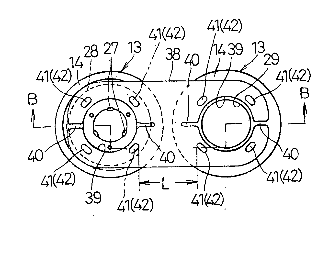
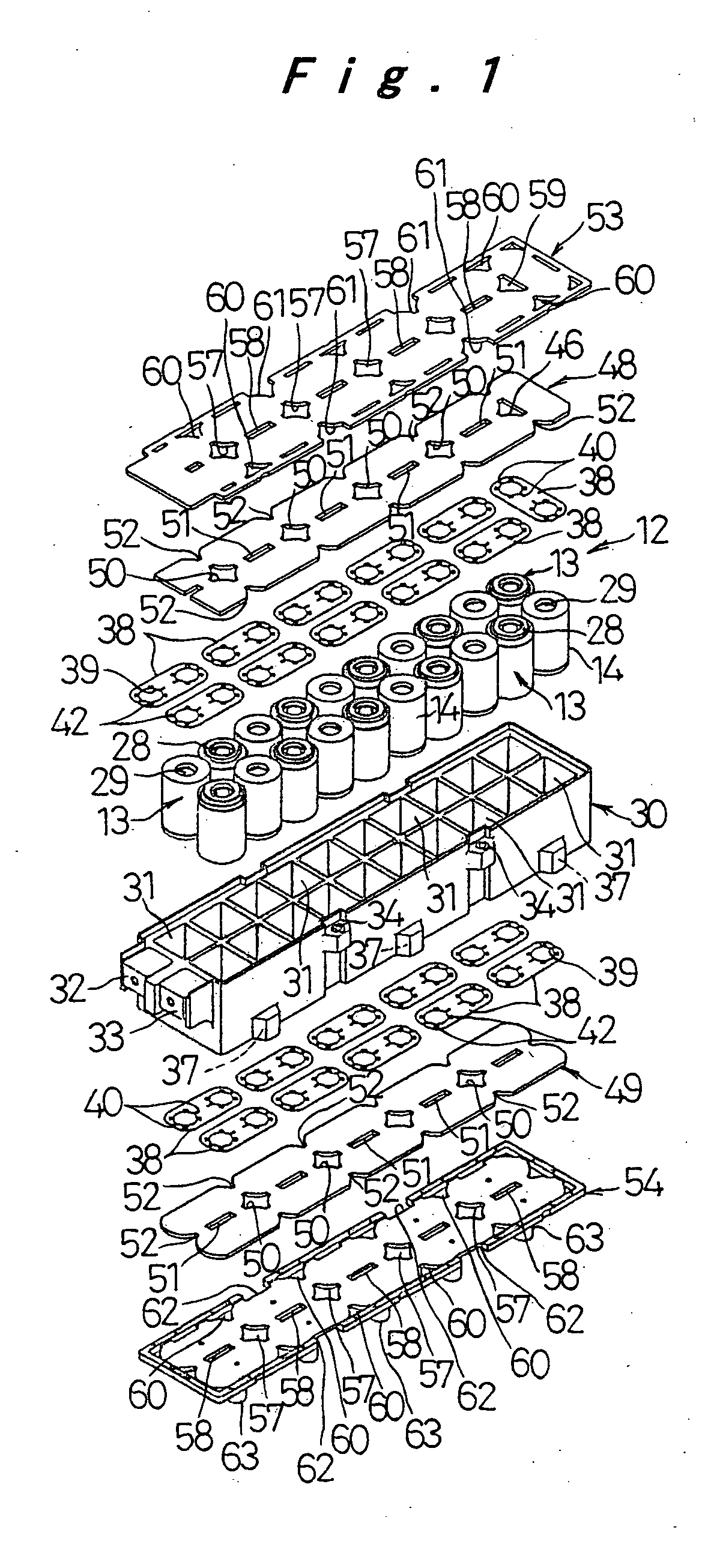
[0039] Preferred embodiments of the present invention are described below, referring to the drawings. FIG. 1 is an exploded perspective view of a battery module 12 according to an embodiment of the present invention, showing the arrangement of components of the battery module 12. In this embodiment, an example is described in which twenty cylindrical cells 13 of the same type and the same standard are connected in series. The cell 13 is a nickel metal hydride battery, for example.

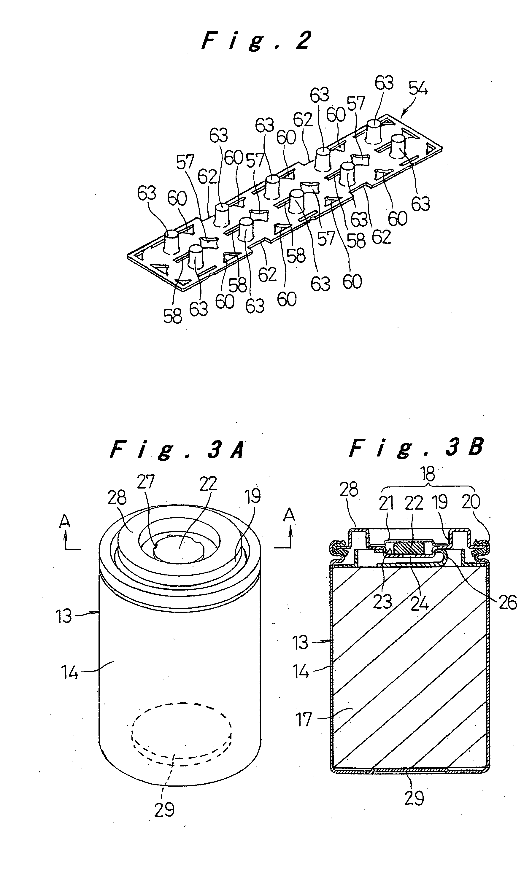
[0040] First, the structure of the cell 13 applied to the above battery module 12 is described. FIG. 3A is a perspective view of the cell 13 and FIG. 3B is a cross-sectional view thereof, taken along line IIIB-IIIB in FIG. 3A. A cell case 14 serving as a negative electrode has a cylindrical shape with a bottom which includes an opening at one end. In the cell case 14 are accommodated an electrode set 17 including an positive electrode plate and a negative electrode plate, that are well-known and are spiral...


PUM

PropertyMeasurementUnit
circumferenceaaaaaaaaaa
structureaaaaaaaaaa
shapeaaaaaaaaaa

Abstract

A connection plate in form of flat plate is welded to be connected to portion that are close to each other, i.e., a connection-electrode portion of one of two adjacent cells and a bottom of a cell case of the other cell, while being bridged between the connection-electrode portion and the bottom of the cell case, thereby forming an inexpensive connecting structure between cells, that reduces the electric resistance, by simple processes. A battery module having a solid structure impervious to vibration or shock is formed by accommodating cylindrical cells in cell-accommodating portions, each of which has a square shape seen from the front, of a holder case made of synthetic resin with their cell axes arranged in parallel, and by closing both sides of the holder case with cover members having radiation holes. Then, a battery pack is formed by attaching outer plates to a plurality of such battery modules that are arranged and integrating them.

Description

TECHNICAL FIELD [0001] The present invention relates to a connecting structure between cells for forming a battery module having a required output voltage by connecting a plurality of cells, a battery module formed by using that connecting structure, and a battery pack formed by arranging and electrically connecting a number of such battery modules and mechanically coupling them. BACKGROUND ART [0002] As a conventional connecting structure between cells for forming a battery module that obtains a required output voltage by connecting a plurality of cells in series, various techniques have been known, for example, as disclosed in Japanese Laid-Open Patent Publication Nos. Hei 10-106533, 2001-126703, and 2000-149907 (hereinafter, referred to as the first, second, and third conventional techniques, respectively). [0003] According to the first conventional technique, as shown in FIG. 15, a dish-like portion of a connector 3 arranged between two cells B1 and B2 is connected to a sealing ...

Claims


Application Information

Patent Timeline
Patent Type & Authority Applications(United States)
IPC IPC(8): H01M50/213H01M50/227H01M50/271B60K1/04H01M50/293H01M50/298H01M50/516H01M50/522H01M50/526
CPCB60L11/1874B60L11/1879B60L2270/145H01M2/1083H01M2/204H01M10/5004Y02T10/7055H01M10/503H01M10/5036H01M10/5065H01M10/5073Y02T10/7005H01M10/5016H01M10/625H01M10/643H01M10/6566H01M10/651H01M10/613H01M10/6562B60L58/26B60L50/64Y02T10/70Y02E60/10H01M50/293H01M50/522H01M50/526H01M50/213H01M50/516H01M50/227H01M50/271H01M50/298
Inventor HIRANO, FUJIO
Owner PANASONIC CORP
Why Eureka
Try Eureka