Environmental clean-up system

a technology of environmental cleanup and environmental protection, which is applied in the direction of steam separation arrangement, combustion types, lighting and heating apparatuses, etc., can solve the problems of cracking of hydrocarbons in soil and waste gases emitted from within the soil tube, and achieve the effect of improving the efficiency of the water vapor generator

Inactive Publication Date: 2005-04-14
JAVAHERIAN MEHRDAD
View PDF44 Cites 10 Cited by
  • Summary
  • Abstract
  • Description
  • Claims
  • Application Information

AI Technical Summary

Benefits of technology

[0005] Accordingly, the present invention provides an efficient high-temperature water vapor generator, which is used to de-contaminate soil. The vapor generator includes a generally cylindrical combustion chamber and a surrounding structure, wherein a cavity is located between the combustion chamber and the surrounding structure. Water is routed through the cavity and into the combustion chamber, where water vapor and heat are generated in the presence of fuel, ignition and air. The heat generated inside the combustion chamber causes the water in the cavity to pre-heat. As a result, the water that is introduced to the combustion chamber is pre-heated, thereby improving the efficiency of the water vapor generator.
[0008] The decontamination process results in waste gases being emitted from within the soil tube. In one embodiment, these waste gases are routed into the vapor generator, thereby burning these waste gases and providing a more efficient system.
[0009] The soil remediation unit of the present invention is compact, and can easily be mounted on a truck bed, a trailer or a barge. Moreover, the vapor generator and drive assembly can be operated in response to one or more portable batteries, a portable fuel supply and a portable (or non-portable) water supply. Thus, the soil remediation unit can be brought to the location where the contaminated soil resides. Because the soil remediation unit decontaminates the soil on-site, there is no need to remove any contaminated soil to a remote location.

Problems solved by technology

That is, hydrocarbons in the soil are cracked by the high temperature.
The decontamination process results in waste gases being emitted from within the soil tube.

Method used


Image

  • Environmental clean-up system
  • Environmental clean-up system
  • Environmental clean-up system

Examples


Embodiment Construction

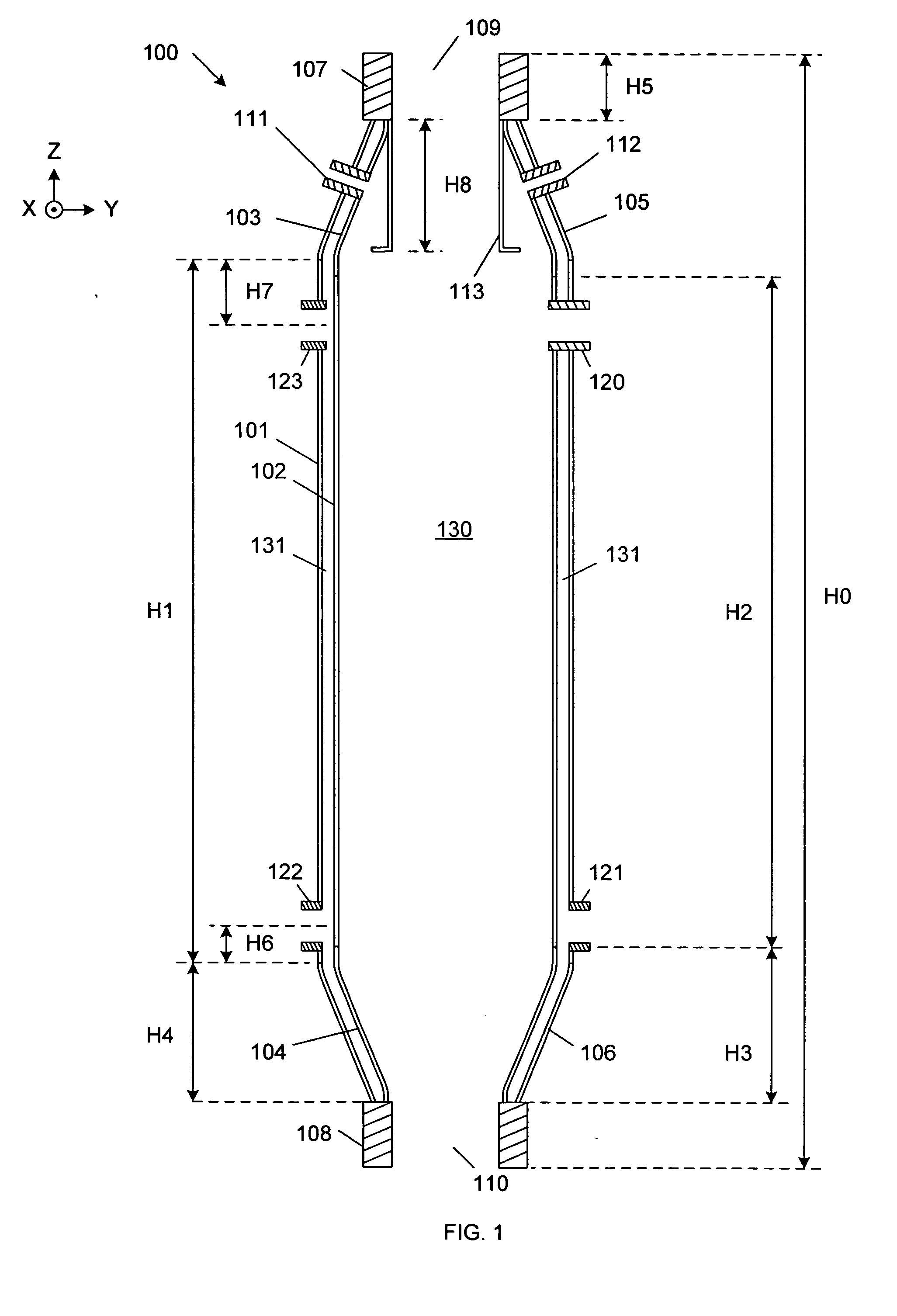
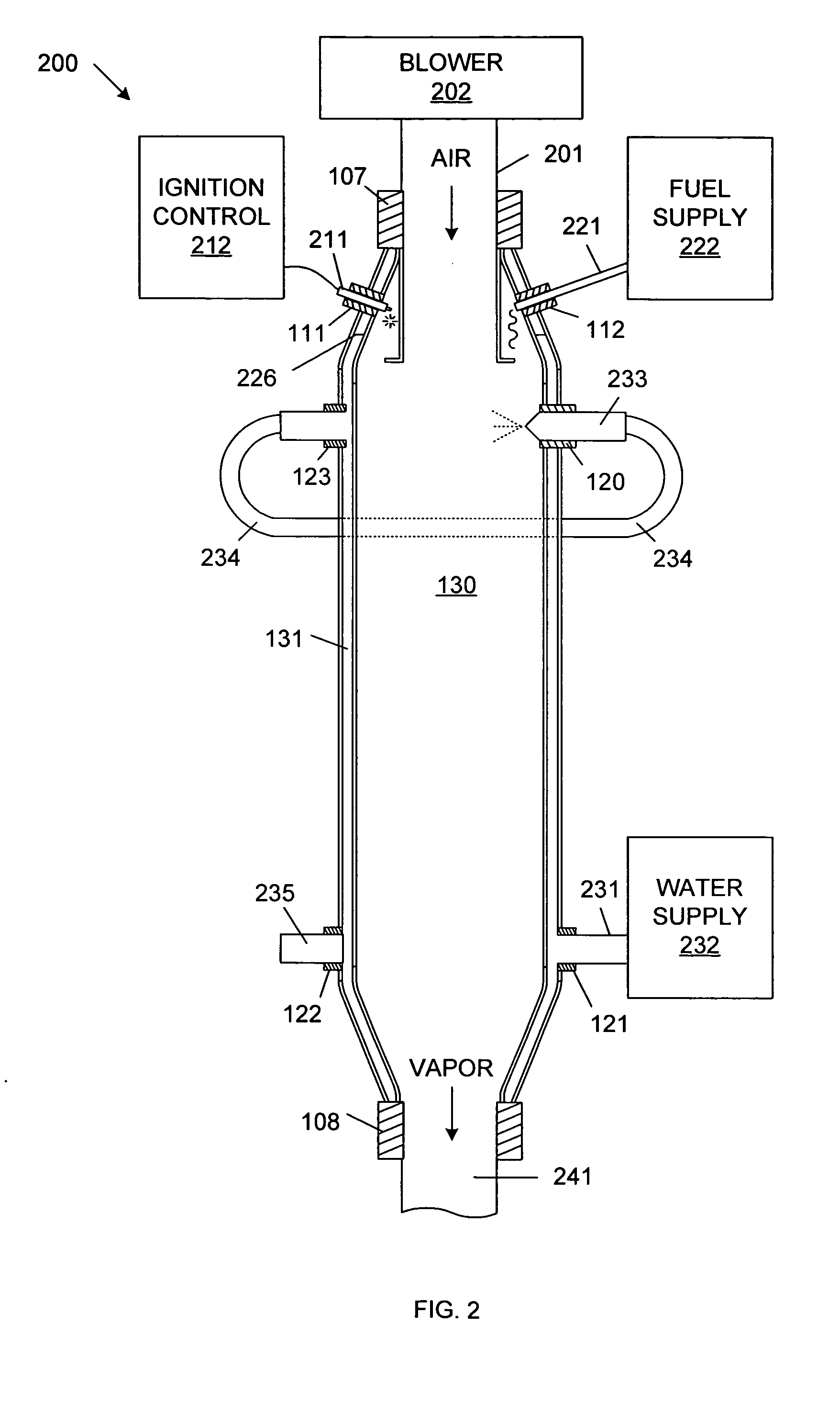
[0016]FIG. 1 is a cross sectional diagram that illustrates a vapor generator 100 in accordance with one embodiment of the present invention. Vapor generator 100 is illustrated with an X-Y-Z coordinate system, as illustrated. Vapor generator 100 is generally cylindrical in nature, with the central axis of the cylinder parallel with the Z-axis.

[0017] Vapor generator 100 includes outer cylindrical section 101, inner cylindrical section 102, a pair of inner conical structures 103-104, a pair of outer conical structures 105-106, an air coupling element 107, a vapor coupling element 108, an ignition coupling element 111, a fuel coupling element 112, vapor baffle element 113, and water coupling elements 120-123.

[0018] In the described embodiment, the elements of vapor generator 100 are made of 304-stainless steel. However, it is understood that vapor generator 100 can be made of other materials in other embodiments. In the described embodiment, vapor generator 100 has a height (H0) of ab...


PUM


Abstract

An efficient high-temperature water vapor generator is used to de-contaminate soil. The vapor generator includes a combustion chamber and a surrounding structure, wherein a cavity is located therebetween. Water is routed through the cavity and into the combustion chamber, where water vapor and heat are generated in the presence of fuel, ignition and air. The generated heat pre-heats the water in the cavity, thereby creating an efficient system. The water vapor is forced into a vapor tube (which has openings for emitting the vapor), thereby heating the vapor tube to temperatures of 800° F. or greater. A soil tube having lifting paddles located therein surrounds the vapor tube. Contaminated soil enters one end of the soil tube. The soil tube is rotated, thereby moving the contaminated soil into contact with the vapor tube (decontaminating the soil). The lifting paddles move the soil toward the second end of the rotating soil tube.

Description

FIELD OF THE INVENTION [0001] The present invention relates to an environmental clean-up system. More specifically, the present invention relates to an efficient system for removing contaminants from soil. BACKGROUND OF THE INVENTION [0002] Soil pollution is becoming a significant problem in this country. In numerous locations around the country, hazardous wastes, such as MTBE's, volatile organic compounds (VOCs), poisons and other chemicals have been inadvertently released, thereby contaminating the surrounding soil. Such soil contamination can be caused, for example, by leaking underground storage tank sites (LUST sites). The hazardous waste may leak through the soil, eventually contaminating water supplies. [0003] Cleaning up contaminated soil is both difficult and costly. Typically, the owner of a site containing contaminated soil is responsible for this soil. However, because there is no cost effective manner of cleaning the soil, the owners of contaminated soil typically pay t...

Claims


Application Information

Patent Timeline
Patent Type & Authority Applications(United States)
IPC IPC(8): A62D3/00B08BB09C1/06F22B1/26F23G5/40F23G7/14F28D7/10F28F5/00
CPCB09C1/06F22B1/26F23G5/40F23G7/14F28F5/00F23G2203/8013F28D7/106F28D2021/0045F23G2203/601
Inventor REINHARDT, ALDON R.
Owner JAVAHERIAN MEHRDAD
Why Eureka
Try Eureka