Apparatus and method for controlling a force-activated controller

a technology of force-activated controller and apparatus, which is applied in the field of apparatus and method for controlling a force-activated controller, aircraft control system, can solve the problems of unobstructed view, heavy and more expensive installation, and the pilot being prevented from using any inherent aircraft maneuverability, etc., and achieves accurate follow-up

Active Publication Date: 2005-04-14
BOMBARDIER CORP
View PDF23 Cites 92 Cited by
  • Summary
  • Abstract
  • Description
  • Claims
  • Application Information

AI Technical Summary

Benefits of technology

[0038] The desired trajectory from the Stick Unit High-Level Controller is relayed to a lower-level servo loop containing a Trajectory Controller in the Stick Unit Low-Level Controller. The Trajectory Controller uses position, rate, and force feedback from one or more sensors mechanically attached to the hand controller system to determine a control signal to the motor control electronics. This element in turn commands an electric motor, which through an optional reduction mechanism, and a coupling mechanism, moves the hand controller according to the desired trajectory. A sensor may be provided to measure one position, rate, and acceleration and other parameters can be derived therefrom by integration or differentiation. Alternatively, individual reasons may be provided for measuring each trajectory parameter. Therefore, when subject to some applied forces, the Trajectory Generator computes the trajectory corresponding to the desired behavior of the hand controller, and the Trajectory Generator makes the latter follow this trajectory. Hence, the hand controller moves according to the desired model, and provides an artificial and controllable feel.
[0039] In one embodiment, the Trajectory Controller takes as an input a desired trajectory and controls the hand controller, through an electric actuator, to accurately follow this trajectory. The Trajectory Controller can be designed to perform equally well on a limited range of trajectory corresponding to the required dynamics for the control task. Hence, if the desired behavior of the stick is changed, or the feel profile is modified, there is no need to adjust the controller gains to satisfy the trajectory tracking accuracy. The Trajectory Controller comprises two parts. A first part uses the measured applied force feedback to compensate the effects of this applied force so that a second part can control the hand controller as if no force were applied to it. This latter point is an important feature of an aspect of the present invention.

Problems solved by technology

This prevents the pilot from using any inherent aircraft maneuver capability in an emergency situation.
This results in a much heavier and more expensive installation than the use of sidesticks.
In addition, sidesticks provide the pilot with an unobstructed view of the instruments and free up valuable space on the cockpit.
The flight control systems used today on all commercial jet transports are exposed to the consequences of a jam in the control system.
Common to all of these systems is that a jam in the flying pilot's controls would require transfer of control to the other pilot and there would be some small period of time where control inputs are lost.
If the jam occurred during the critical part of the flight, such as during take off or final approach, there may not be sufficient time to regain control and prevent a catastrophic event.

Method used


Image

  • Apparatus and method for controlling a force-activated controller
  • Apparatus and method for controlling a force-activated controller
  • Apparatus and method for controlling a force-activated controller

Examples


Embodiment Construction

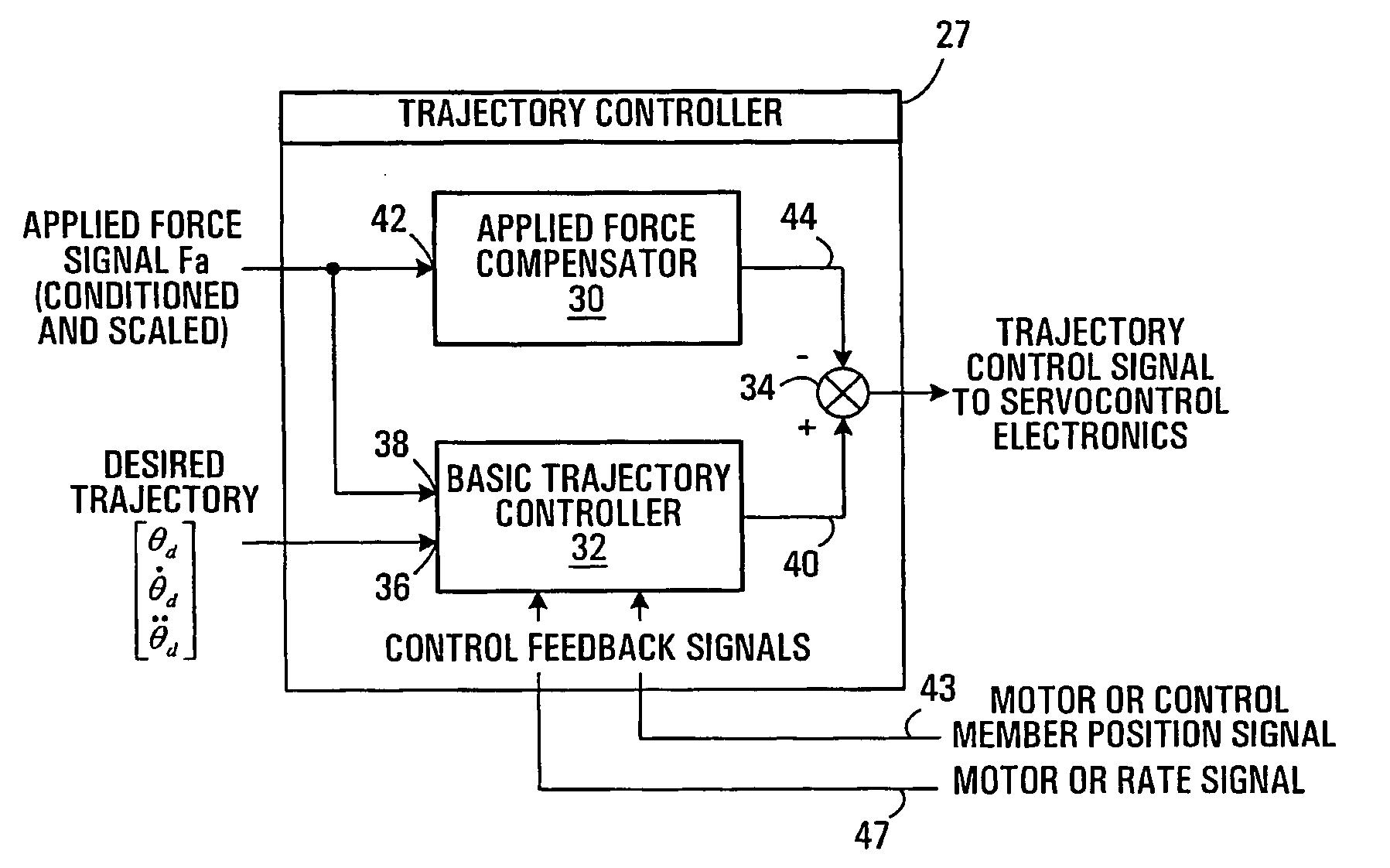
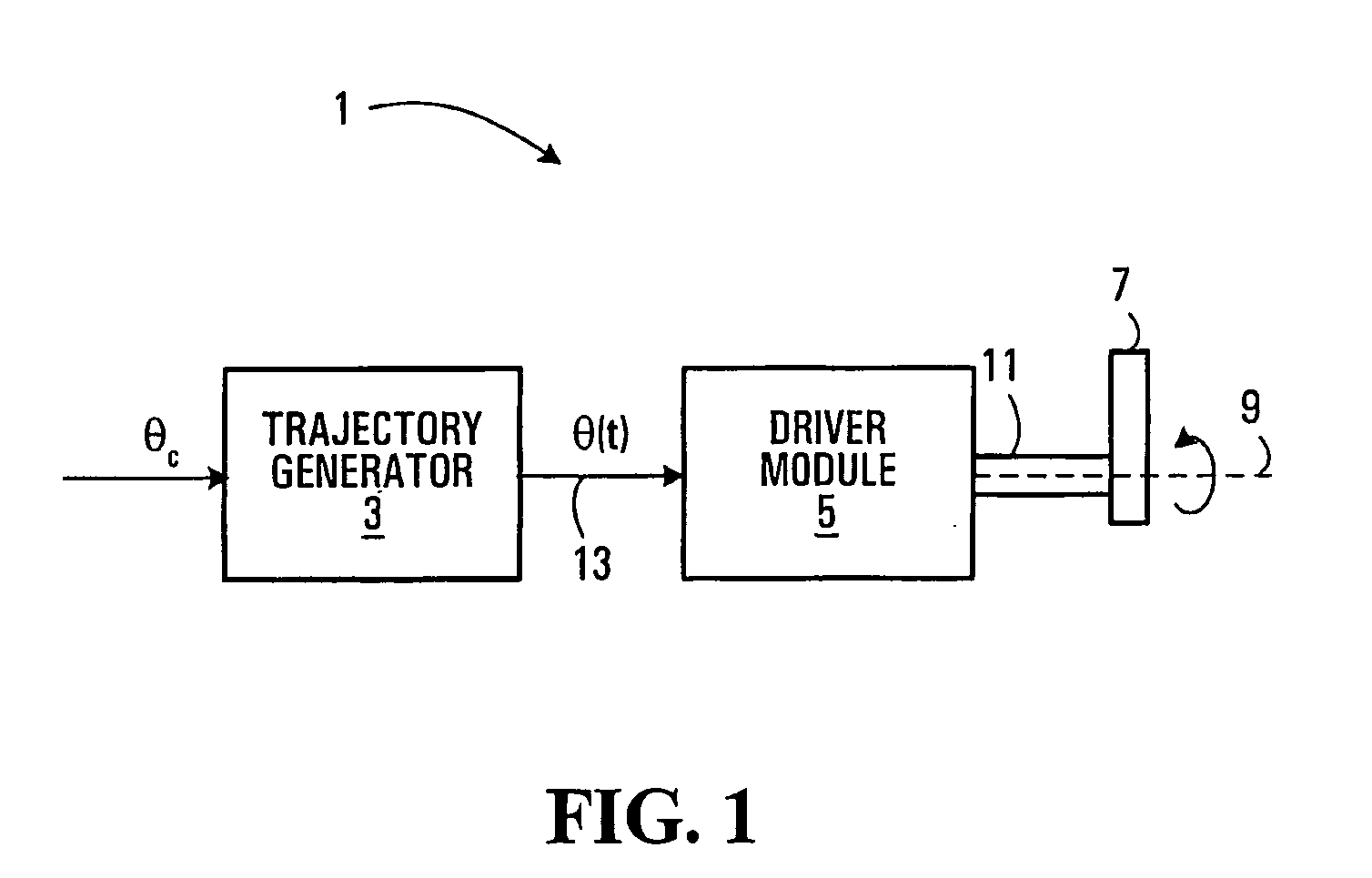
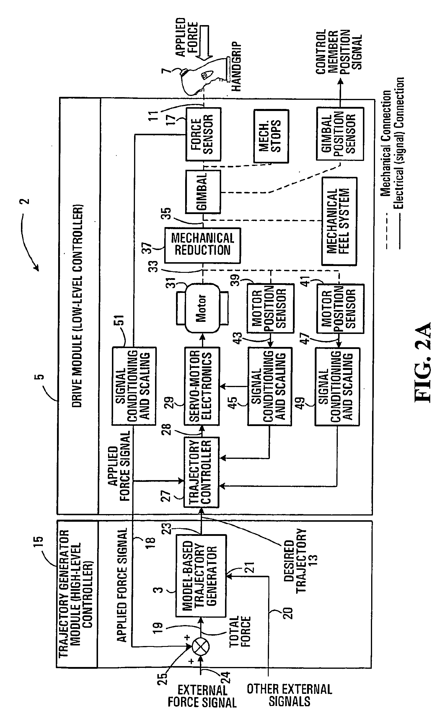
[0104] In the following, the term stick will be used synonymously to (active) hand controller. Moreover, it is assumed to apply equally to sidestick and centerstick type of hand controllers as well as other controllers for example operated by other parts of the body e.g. a foot or feet. Although embodiments of the invention are described for an application to aircraft, it is applicable to any system requiring similar control functionality; for example, this includes rotorcraft, various types of ground vehicles including specialized machinery (e.g. construction, mining, forestry industries), water surface vehicles, underwater vehicles, spacecraft, and robotic manipulators. The embodiments described herewith apply to individual degrees-of-freedom of control of hand controllers. Therefore, although reference will be made to hand controllers providing two mutually perpendicular degrees-of-freedom of control, namely pitch and roll axes for an aircraft, aspects the invention can be applie...


PUM


Abstract

A servo controlled system is disclosed for providing simulated feel equivalent to that of traditional mechanical hand controllers using servomotors. Position and force sensor signals are processed and used in a feedback loop that controls the motor mechanically connected to the stick. The overall feedback loop is comprised of a low-level motor feedback loop, and high-level force feel loop. The two loops have associated performance parameters that can be specified independently. The high-level feel force loop is comprised of a static and dynamic performance components. Static and dynamic performance components can be specified independently. The system allows variable and/or additional force cues to be specified externally to the system and felt by the operator. The system also allows external signal to backdrive die stick to follow a specified motion. The control framework permits the electronic coupling of the motion and applied forces of pilot and co-pilots in a dual arrangement while retaining the above-mentioned features. It also allows asymmetric force feel gradients to be implemented for each stick, or for a stick relative to a second one. A zero breakout or detent can be provided at the stick null displacement. For cross-coupled sticks, the detent can be shared as in a mechanically cross-coupled system, implemented independently on each slick, or any combination of these two. The control framework also provides the simulation of mechanical compliance in the cross-coupling of the two sticks in case of a jam or of force fight between the pilots, and automatic de-coupling of the sticks.

Description

FIELD OF THE INVENTION [0001] The present invention generally relates to control systems, for example, aircraft control systems, and in particular, but not limited to manual control devices such as hand controllers for use with a fly-by-wire control system that are driven electrically in response to hand movement. BACKGROUND OF THE INVENTION [0002] Over the years, the flight control systems have evolved from simple cable systems, where the pilot had to provide the force to overcome the aerodynamic hinge moments on the control surfaces, to today's fly-by-wire (FBW) systems, where computers signal surface actuators to provide a closed loop maneuver trajectory in response to pilot inputs. Prior to the advent of FBW technology, the flight control systems on commercial airplanes used cables to relay pilot commands to the flight control actuators and / or control surfaces. Even with powered controls, the control system friction was so high that the pilot required a high mechanical advantage...

Claims


Application Information

Patent Timeline
Patent Type & Authority Applications(United States)
IPC IPC(8): B64C13/04B64C13/10B64C13/12B64C13/46B64C13/50
CPCB64C13/04B64C13/10B64C13/503B64C13/46B64C13/12B64C13/0421
Inventor TESSIER, CLAUDEMARTINEAU, JONATHAN
Owner BOMBARDIER CORP
Why Eureka
Try Eureka