Supercharge Your Innovation With Domain-Expert AI Agents!

Material determination system and method

a material and determination system technology, applied in the field of material determination system and method, can solve the problems of not always clearly detecting the difference that is supposed to be found in the reception signal due to any material difference, and the conventional system often complicates the determination method, so as to achieve a wider surface area and high precision

Inactive Publication Date: 2005-04-21
SEIKO EPSON CORP
View PDF8 Cites 8 Cited by
  • Summary
  • Abstract
  • Description
  • Claims
  • Application Information

AI Technical Summary

Benefits of technology

[0013] In still another aspect of the present invention, the ultrasonic signal transmission / reception section transmits ultrasonic signals of various frequencies over a predetermined frequency band toward the object at a plurality of given points scattered across a range that covers at least half or more of the object's surface area. Such a structure allows material determination with high precision by using a wider surface area of the object for detection.
[0014] In still another aspect of the present invention, the ultrasonic signal transmission / reception section transmits ultrasonic signals of various frequencies over a predetermined frequency band toward the object at all or each of a plurality of given points scattered within a range that covers, at the most, less than half of the object's surface area. Such a structure allows for material determination in a short amount of time by confining the surface area of the object for detection.

Problems solved by technology

With such a relatively narrow frequency band, however, a difference that is supposed to be found in a reception signal due to any material difference may not always be clearly detected.
To detect such a minute difference, the conventional system often complicates the determination method, or requires an ultrasonic transducer to have a highly-precise property.

Method used


Image

  • Material determination system and method
  • Material determination system and method
  • Material determination system and method

Examples


Embodiment Construction

[0025] Below, an embodiment of a material determination system according to the present invention is described with reference to the accompanying drawings. In the embodiment, printing paper is presumably an object for a material determination.

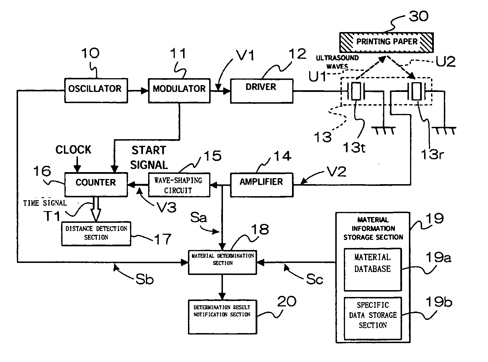
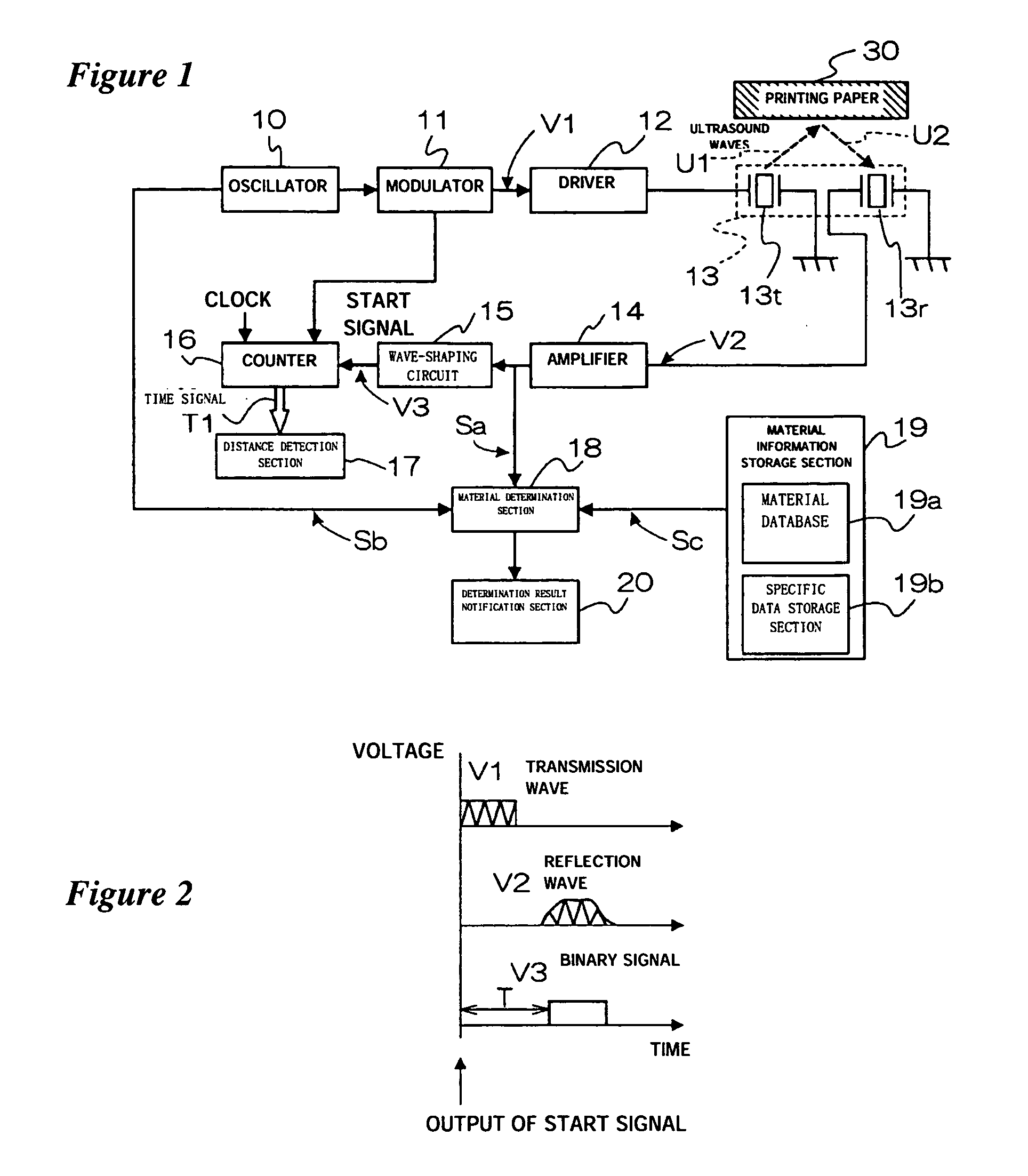
[0026]FIG. 1 is a block diagram showing the structure of a material determination system of the present invention, and FIG. 2 is a waveform diagram of a temporal voltage change observed for the respective operating components. In FIG. 1, an oscillator 10 generates an alternating signal while repeatedly varying (sweeping) the frequency in a given time period over a frequency band in the range of 40 kHz to 100 kHz, or more. A modulator 11 repeatedly outputs a rectangular wave signal of a predetermined time frame as a result of a modulation using an output signal from the oscillator 10. The modulator 11 also outputs a start signal that indicates the output start time of the corresponding rectangular wave signal. Refer to FIG. 2 for a waveform V1 ...


PUM


Abstract

A structure including an ultrasonic transducer, a material database, and a material determination section. The ultrasonic transducer transmits ultrasound signals of a plurality of frequencies toward a printing paper over a frequency band covering 40 kHz to 100 kHz or more, and receives reflection signals. The material database stores information representing a reception signal on a material basis. The material determination section makes a material determination for the printing paper based on the information stored in the material database, and the signal (signal derived by amplifying a signal) received by the ultrasonic transducer.

Description

FIELD OF THE INVENTION [0001] The present invention relates to a determination system and method suitable for a printer to automatically define a printing paper by its material. DESCRIPTION OF THE RELATED ART [0002] An ultrasonic transducer is conventionally used for thickness and distance measurement, and material determination. Such an ultrasonic transducer transmits and receives ultrasonic signals, and includes an ultrasonic sensor. [0003] Conventionally, such an ultrasonic transducer used for thickness and distance measurement, and material determination, is often a resonant type that uses piezoelectric ceramics. A resonant type ultrasonic transducer has transmission or reception properties serving well with a specific resonance frequency that is constructively determined. [0004] A material determination system including an ultrasonic transducer generally uses a factor to determine what kind of material an object is made of. The factor is a difference observed in an ultrasonic s...

Claims


Application Information

Patent Timeline
IPC IPC(8): B41J11/42B65H7/02G01N29/00G01N29/11G01N29/34G01N29/44
CPCG01N29/11G01N29/348G01N2291/101G01N2291/0289G01N2291/044G01N29/4436
Inventor MATSUZAWA, KINYA
Owner SEIKO EPSON CORP
Features
  • R&D
  • Intellectual Property
  • Life Sciences
  • Materials
  • Tech Scout
  • Unparalleled Data Quality
  • Higher Quality Content
  • 60% Fewer Hallucinations
Learn More