Charge pump for phase-locked loop

a charge pump and phase-locked loop technology, which is applied in the direction of oscillation comparator circuits, instruments, pulse automatic control, etc., can solve the problems of phase detectors that reset the charge pump to the high impedance state too soon or too late, vco can change phase, etc., to reduce phase noise or jitter in the charge pump, minimize the effect of dead bands, and minimize the dithering of the charge pump

Inactive Publication Date: 2005-04-21
PROCOMM
View PDF1 Cites 11 Cited by
  • Summary
  • Abstract
  • Description
  • Claims
  • Application Information

AI Technical Summary

Benefits of technology

[0006] An object of this invention is to minimize the effect of the dead band in a charge pump of a phase detector in a phase locked loop. Another object of this invention is to minimize the dithering in charge pump of a phase detector (i.e., to reduce the phase noise or jitter in the charge pump). Still another object of this invention is to balance the delays of the p-channel and n-channel MOSFET which provide the charging and discharging output currents.

Problems solved by technology

The design has two problems: First, the VCO can change phase without producing a significant phase comparator output to activate the charging and discharging mechanism.
Second, there is a time delay between the time phase comparator sending an output signal and the time the charge pump completely respond to the signal and turn on or off the output currents accordingly.
Conventional design is to add a delay to the reset signal, but the added delay cannot track with the charge pump, thus causing the phase detector to reset the charge pump to the high impedance state too soon or too late.
If resetting the charge pump too late then both the sourcing and sinking currents will exist for an excessively long time and produce no useful output current.
Under such situation, the thermal and shot noises generated in the sourcing and sinking devices in the charge pump will increase the VCO phase noise.
However, since the delay chain does not track the “real” delay in the charge, the reset signal may by too early or too late.
If this happens, the charge performs poorly and the phase-locked loop may degrade its performance or cause instability.
If the reset signal appears too late, the can be a significantly long period of time that both the sourcing and sinking currents exist.
If this happens, the sourcing and sinking currents cancel each other and result in nearly “zero” charge output current and degrade the PLL performance.

Method used


Image

  • Charge pump for phase-locked loop
  • Charge pump for phase-locked loop
  • Charge pump for phase-locked loop

Examples


Embodiment Construction

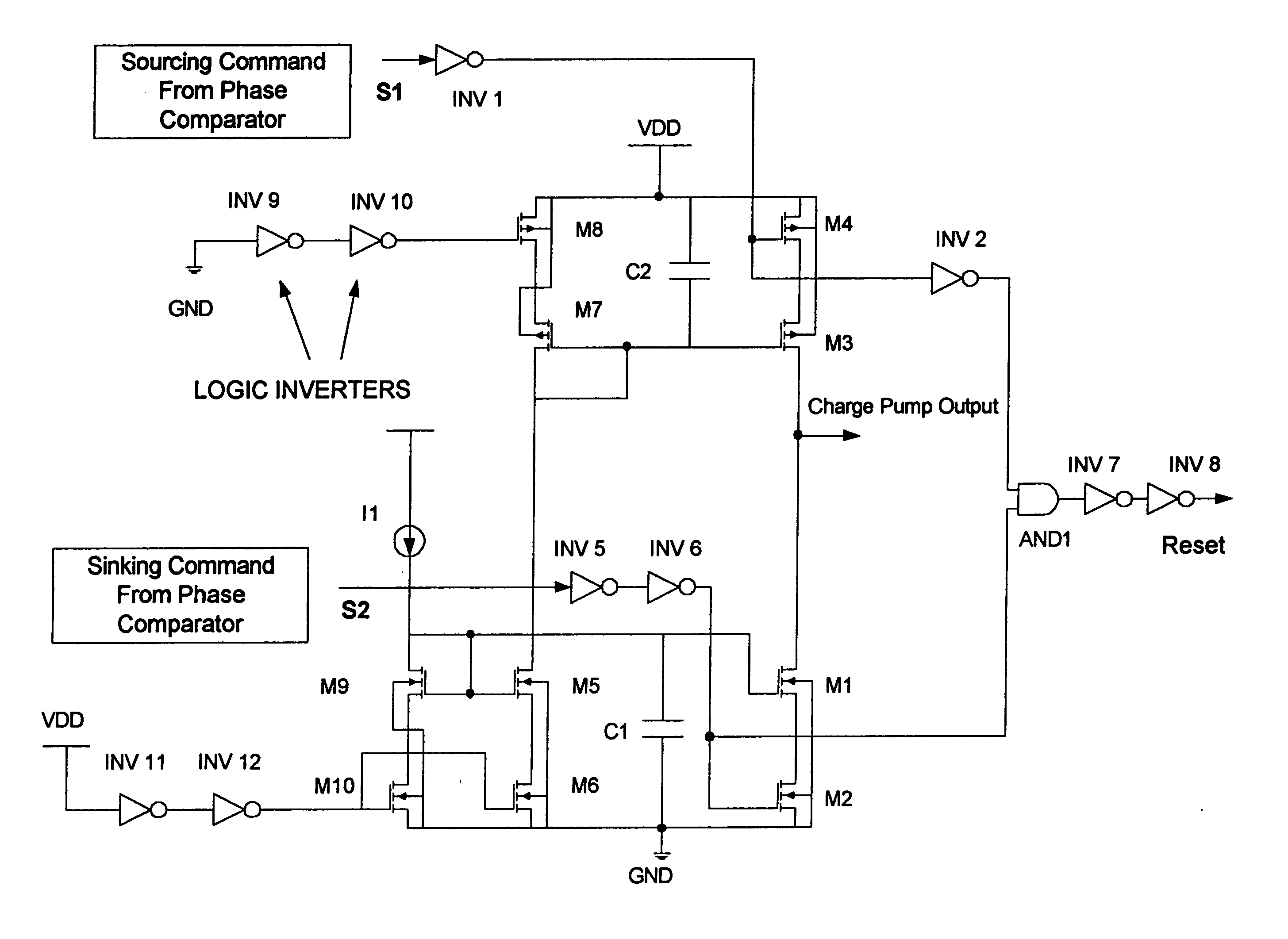
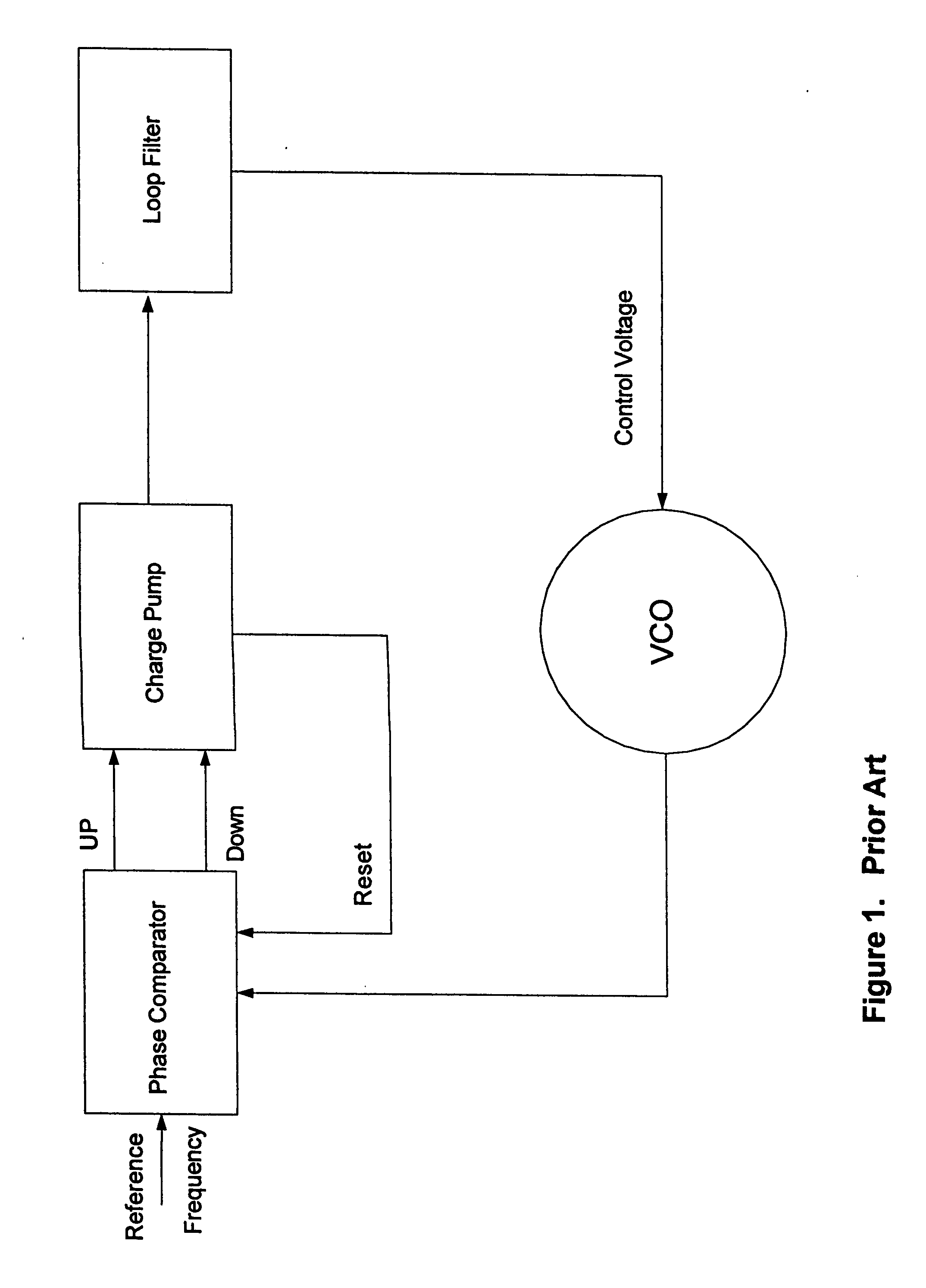
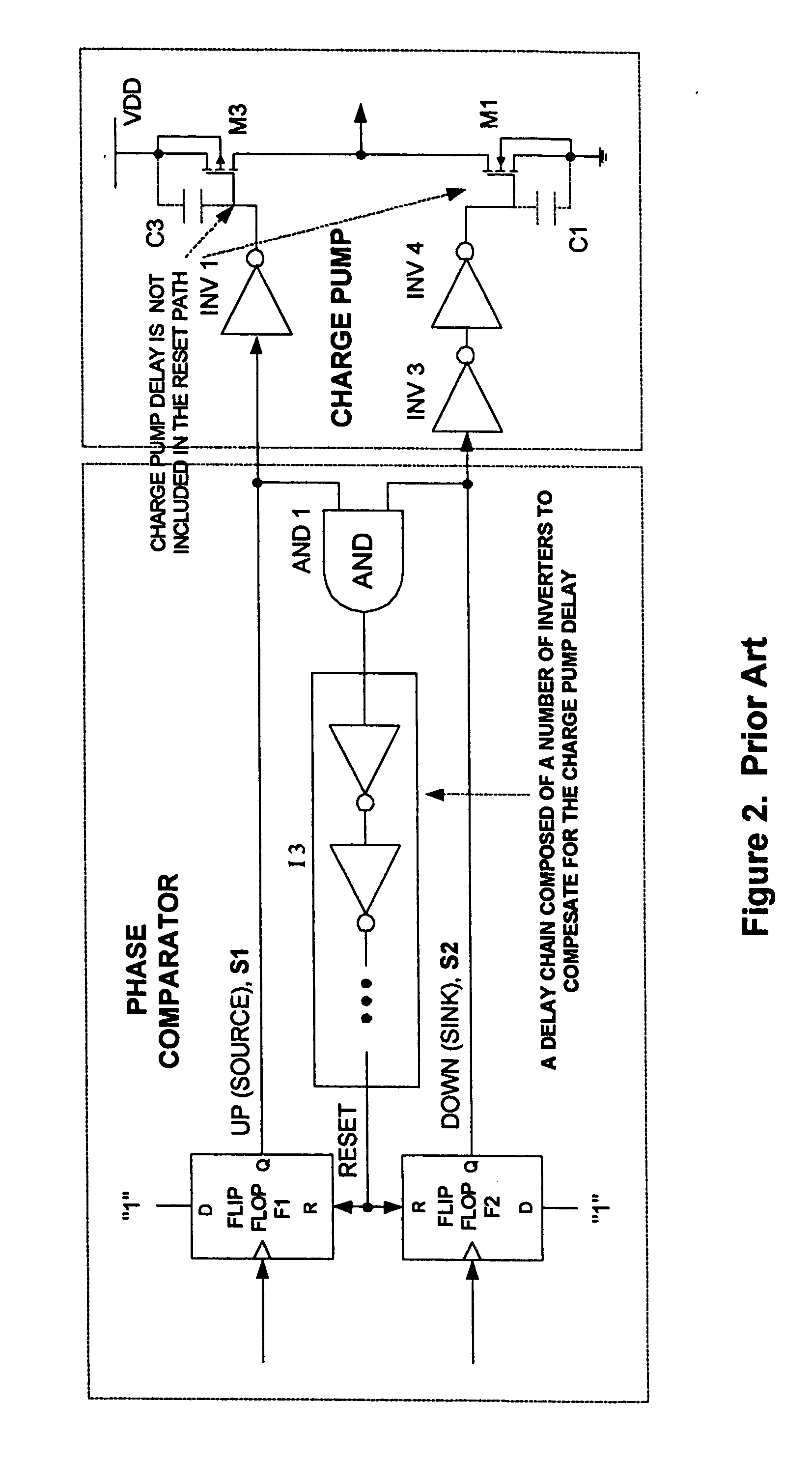
[0013]FIG. 3 shows the block diagram of the present invention. The block diagram is similar to the prior art FIG. 2. Same reference numerals correspond to the same functions as that in FIG. 2. The differences are: (1) the RESET signal is derived from the gate inputs to the complementary charge pump output switches M1 and M3 through AND gate AND1, and (2) the delay chain of inverters 13 in FIG. 2 is eliminated, and (3) an inverter INV2 is inserted between the input to the gate of M3 and the upper input to the AND gate. In this design, the reset path includes the delay of the charge pump. By doing so, even with process variation or temperature effects, the reset signal is never too early or too late and the phase comparator and the charge pump work coordinately.

[0014]FIG. 4 shows a first embodiment of the present invention. M1(NMOS) and M3 (PMOS) compose of the output charge pump stage. M3 sources current to the charge pump output and M1 sinks the current from the output. M1 and M3 a...


PUM


Abstract

When both the sourcing command and the sinking command to the phase comparator are high, the charge pump phase detector creates a high impedance output dead period, which is undesirable. The dead zone can be minimized by resetting the phase comparator when both sourcing command and sinking command are high. Accurate timing of the reset signal is crucial to good PLL phase noise performance and also to the elimination of the dead zone problem. In our invention, accurate reset timing is achieved by including the charge pump delay time caused by the input gate capacitance of the output complementary MOSFETs in the reset signal path.

Description

BACKGROUND OF THE INVENTION [0001] (1) Field of the Invention [0002] This invention relates to phase detector in a phase-locked loop, in particular to the charge pump of the phase comparator. [0003] (2) Brief Description of Related Art [0004]FIG. 1 shows a commonly used basic phase-locked loop (PLL) for a frequency synthesizer. A voltage controlled oscillator (VCO) generates a frequency to compare with a reference frequency in a phase comparator. The output of the phase comparator is used to feed a phase detector. In frequency synthesizers, a widely used method for phase detection is to use a charge pump after a phase comparator to derive a DC voltage for controlling the voltage-controlled oscillator (VCO). The charge pump charges a capacitor when the phase comparator output is UP, and discharges the capacitor when the phase comparator output is DOWN. The DC voltage changes the frequency of the VCO until the VCO generates a frequency, which is locked in phase with a reference freque...

Claims


Application Information

Patent Timeline
Patent Type & Authority Applications(United States)
IPC IPC(8): H03L7/085H03L7/089
CPCH03L7/0895H03L7/085
Inventor CHIEN, HWEY-CHING
Owner PROCOMM
Why Eureka
Try Eureka