
System and method for mapping diaphragm electrode sites

Inactive Publication Date: 2005-04-21
RMX
View PDF99 Cites 233 Cited by
  • Summary
  • Abstract
  • Description
  • Claims
  • Application Information

AI Technical Summary

Benefits of technology

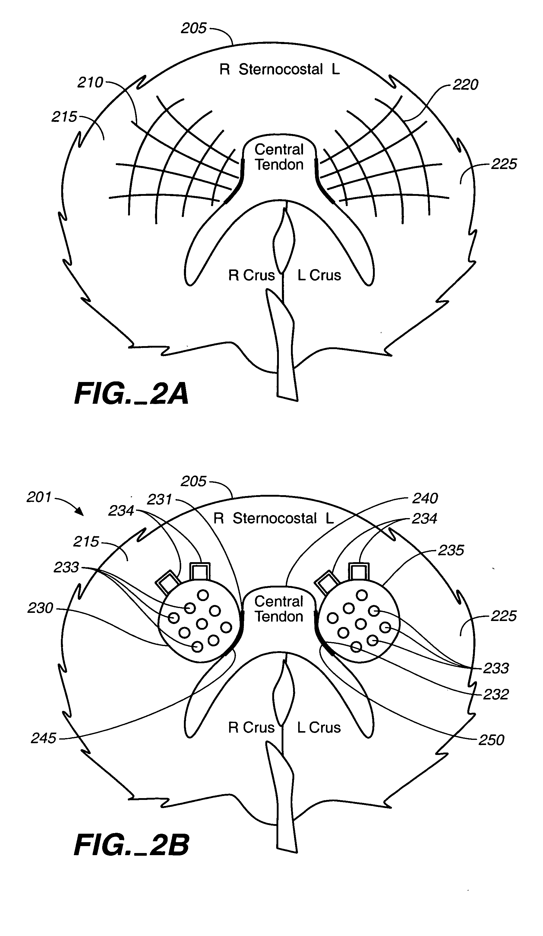
[0018] In another embodiment a support structure supporting one or more electrodes is configured to be placed on the surface of the diaphragm. The support structure may be, e.g., a mesh or other flexible thin substrate. The support structure may comprise a variety of materials such as, e.g., silicone, PTFE, polyurethane, latex, polyester. The support structure may be a substrate with electrodes positioned on, attached to, or formed with the substrate. The substrate may be configured to be positioned on the diaphragm, e.g., by aiding proper locating, positioning and placement of the electrodes and / or by accommodating the movement of the diaphragm. The substrate may also be shaped to fit on the diaphragm and may also be keyed with anatomical structures to aid in ideal positioning. Electrical stimuli are applied sequentially and / or in combination through the electrodes to the diaphragm to elicit a natural breathing response from the diaphragm.

Problems solved by technology

Although electrode placement for obtaining full activation may be achieved by mapping a motor point, there are situations in which full activation may not be desirable, e.g., in the treatment of sleep apnea, because it may disturb the sleep of the subject.
Such peak or integrated value is not believed to be sufficient to determine proper placement of electrodes to achieve a desired breathing morphology because placement of electrodes influences the coordinated activation of various nerve and muscle fibers.
Motor point mapping as performed in the prior art, for example, does not provide the information necessary for optimal placement of therapeutic electrodes intended to stimulate breathing patterns similar to those associated with certain activity levels such as, e.g., sleep.
Also, tidal volume is not believed to provide sufficient information for optimal placement of electrodes to provide other desired inspiration morphologies that are characterized by flow properties.
Threshold and full activation mapping have been done under these conditions, but it is not believed to be well suited for mapping that is directed to identifying optimal electrode placement for replicating intrinsic breathing patterns or for controlling or manipulating specific aspects of breathing morphology and related physiology.
In this scheme there may be some placement error when the mapping electrode is removed and replaced with a permanent implanted electrode.

Method used


Image

  • System and method for mapping diaphragm electrode sites
  • System and method for mapping diaphragm electrode sites
  • System and method for mapping diaphragm electrode sites

Examples


Embodiment Construction

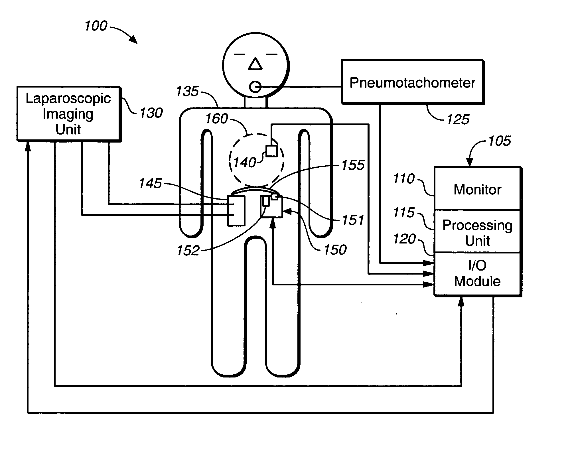
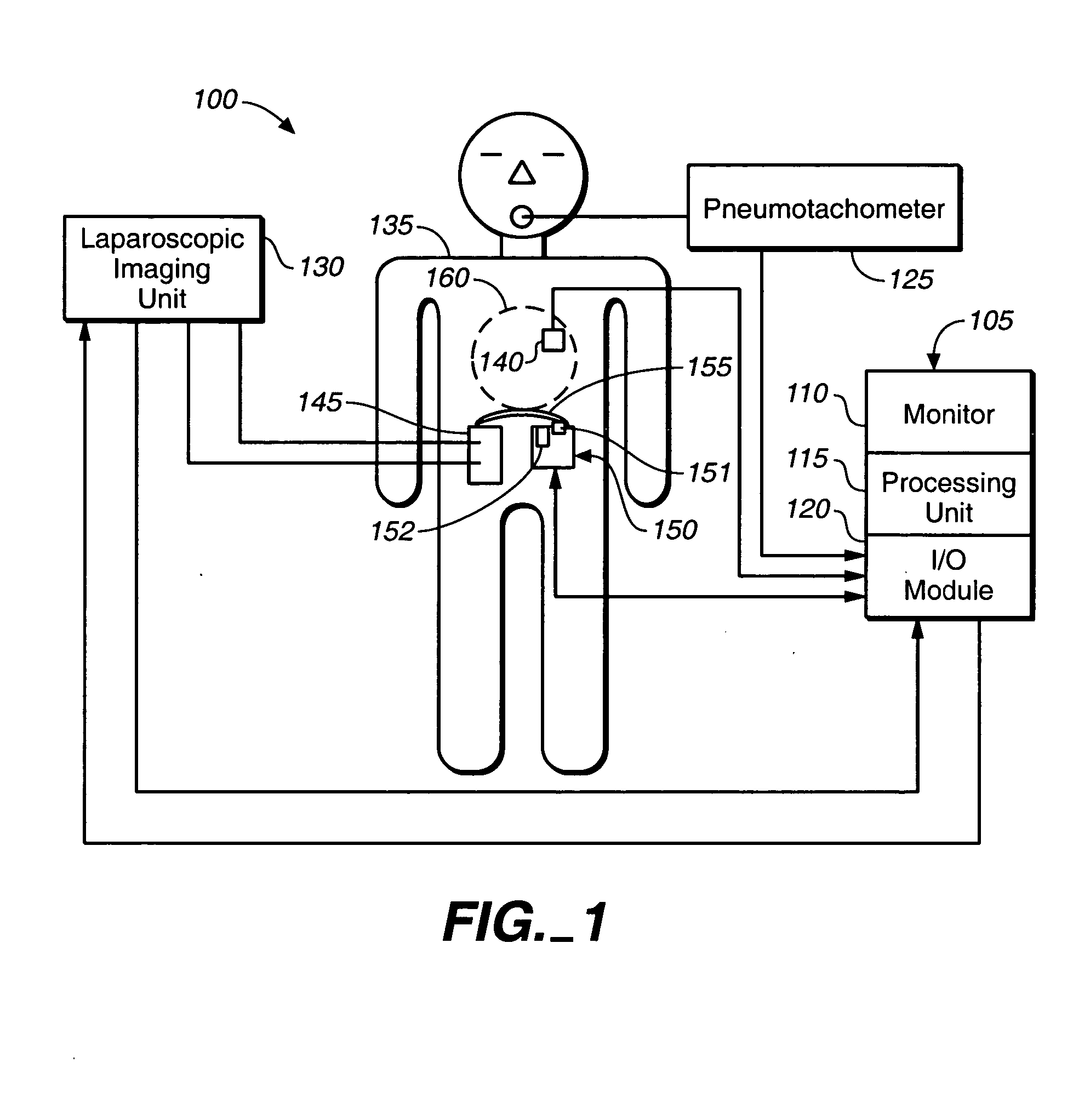
[0053]FIG. 1 shows a system 100 for mapping electrode sites on a diaphragm 155 of a subject 135. A laparoscopic imaging unit 130 is coupled to a laparoscope 145 for observing the surface of the diaphragm 155. The imaging unit 130 is coupled to a diaphragm mapping control module 105. The imaging unit 130 may provide analog or digital images to the control module 105. The control module 105 includes a monitor 110, processing unit 115 and an I / O module 120.

[0054] The monitor 110 may be used displaying a graphical user interface and may also be used for displaying images. Displayed images may be either real-time images from the imaging unit 130 or stored images. Stored images may be overlaid with real-time images to provide visual references for electrode placement.

[0055] The processing unit 115 includes a data processor, memory, and program storage for data and image acquisition and manipulation. The processing unit 115 is coupled to an input / output (I / O) module 120, and may be used ...


PUM


Abstract

A signal source coupled to one or more electrodes in the vicinity of the diaphragm for mapping therapeutic electrode sites. A stimulus signal from the signal source may be applied to the one or more electrodes to produce activation of the diaphragm. Activation of the diaphragm is sensed to provide information that may be correlated with the stimulus signal. The correlated information may be used to identify a therapeutic locus for a therapeutic electrode. An electrical stimulus comprising a series of pulses may be applied to the one or more electrodes to elicit a desired breathing response. The electrical stimulus may be applied between intrinsic breathing cycles, or between regulated breathing cycles. More than one electrode may be supported on a single substrate. The substrate may configured to be positioned on the diaphragm. A hierarchy of stimuli may be applied to a set of electrodes.

Description

CROSS-REFERENCE TO RELATED APPLICATIONS [0001] This application is a continuation-in-part to U.S. patent application Ser. No. 10 / 686,891, “BREATHING DISORDER DETECTION AND THERAPY DELIVERY DEVICE AND METHOD”, by Tehrani filed Oct. 15, 2003, and incorporated herein by reference.FIELD OF THE INVENTION [0002] The present invention relates to devices, systems, and methods useful for determining locations for therapeutic electrode placement on the diaphragm. BACKGROUND [0003] Electrical stimulation of the diaphragm has been performed by delivering a stimulus to the diaphragm through one or more electrodes. The location of the stimulation electrodes greatly affects the ability to obtain a desired response with a given stimulus and candidate electrode sites may be mapped in order to aid in selecting a location for electrode placement. [0004] Diaphragm mapping is the process of correlating electrical stimuli applied at a set of points in the vicinity of the diaphragm muscle with the associa...

Claims


Application Information

Patent Timeline
IPC IPC(8): A61B5/0488A61B5/08A61N1/36
CPCA61B5/0488A61B5/08A61N1/36132A61B5/7264A61N1/3601A61B5/4818A61B5/389A61B5/395
Inventor TEHRANI, AMIR J.LEE, CHANGLIGON, DAVIDMELTZER, MARKMO, ANTHONY
Owner RMX
Learn More