
Lever-mechanism motor or pump

Inactive Publication Date: 2005-04-28
RANTALA VEIKKO KALEVI
View PDF6 Cites 1 Cited by
  • Summary
  • Abstract
  • Description
  • Claims
  • Application Information

AI Technical Summary

Benefits of technology

[0008] One advantage in hot-air engines over, for example, conventional internal combustion engines, is that the exhaust gases are relatively clean, having a low carbon dioxide content and practically no unburned hydrocarbons.
[0012] The greatest advantages of the rotary-piston engine, compared to a conventional engine equipped with a piston with linear movement, are the evenness of its operation, the evenness of its torque, the small number of parts subject to wear, its light weight, and its basic simplicity.
[0015] The present invention is intended to help to improve the utilization of energy and create an machine, engine, or pump operating on the lever-mechanism principle, which is efficient, because it can exploit the entire pressure difference of the medium, while also containing few moving parts, the paths of travel of which are short and the sealing of which can be easily arranged, and has friction that is mainly the rolling friction in the bearing, the whole device having a construction that is multi-purpose, simple, and light. An engine according to the invention has a wide torque range, while the effective surface area of the pistons is great in relation to the volume of the cylinder.
[0017] An apparatus according to the invention can also be used to exploit relatively low-temperature energy. The engine also does not need external cooling, when using a source of high-temperature energy or ‘residual’ energy from some other device, being instead able to function as a radiator and / or cooler itself, while simultaneously increasing the overall efficiency.
[0018] When a machine according to the invention is used as an engine, it creates a small pollution load and can even be used to reduce the polluting effect of the exhaust gases of some other engine, as will be described later. These characteristics also extend the use of the engine to certain special applications.

Problems solved by technology

However, their drawbacks include the large size of the total device, the need for continual monitoring of its operation, and the need for servicing, due to the accumulation of soot and boiler scale.

Method used


Image

  • Lever-mechanism motor or pump
  • Lever-mechanism motor or pump
  • Lever-mechanism motor or pump

Examples


Embodiment Construction

[0025] In the following, general reference will only be made to an engine, as it is simpler and because a pump uses the technical components as such of the solutions according to the invention. Thus, reference to an engine is intended to apply to all embodiments of the invention. On the other hand, in the following, general reference will be made to the invention, using even highly detailed and restricted definitions of its various components. However, this is only done for the sake of clarity, the terms used representing only one example of mutually equivalent alternative forms of the component in question.

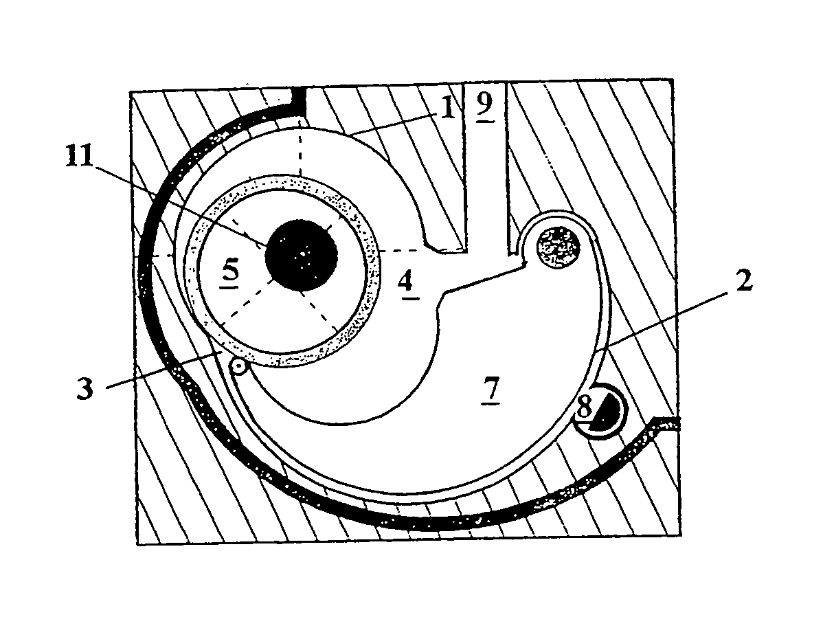
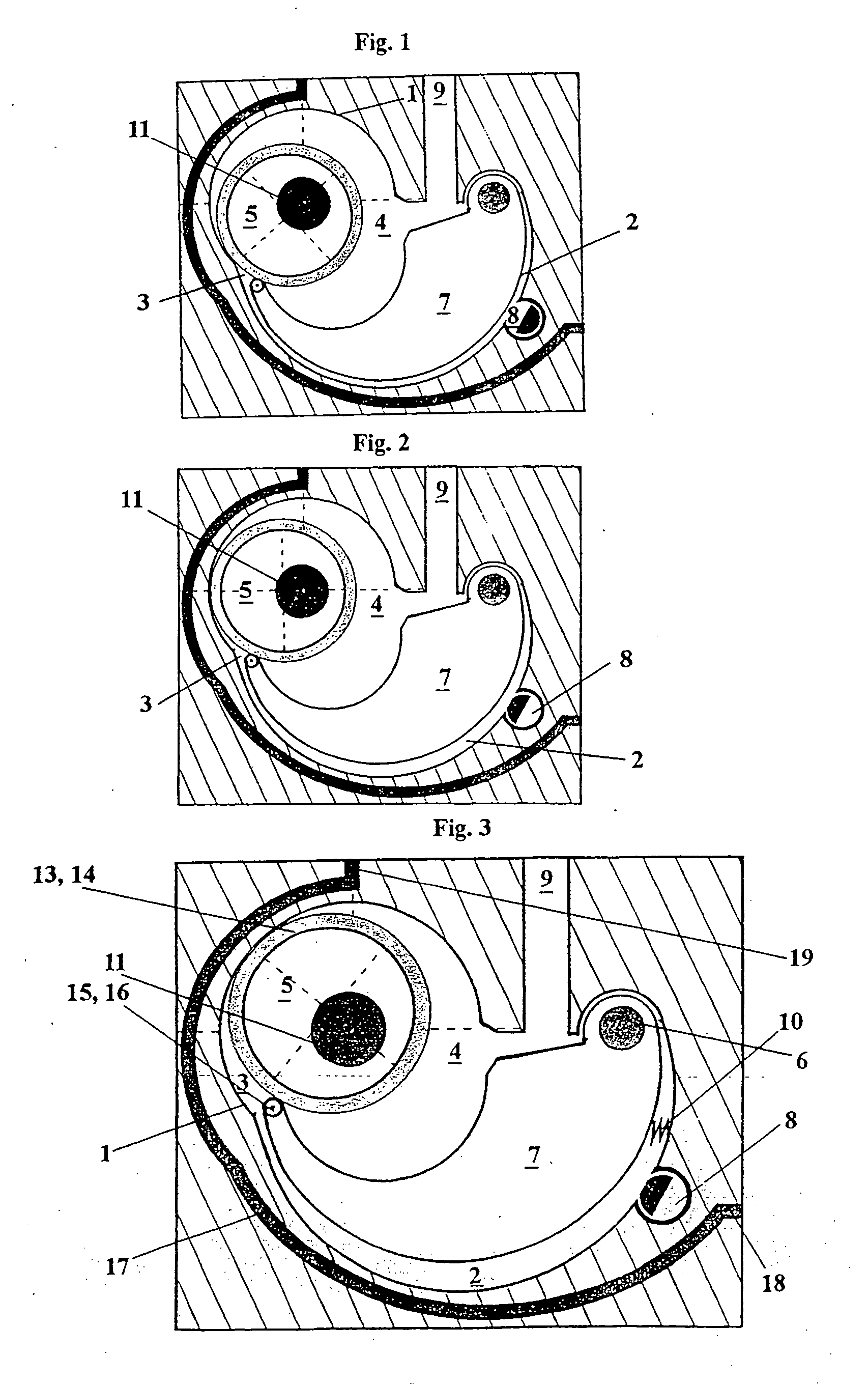
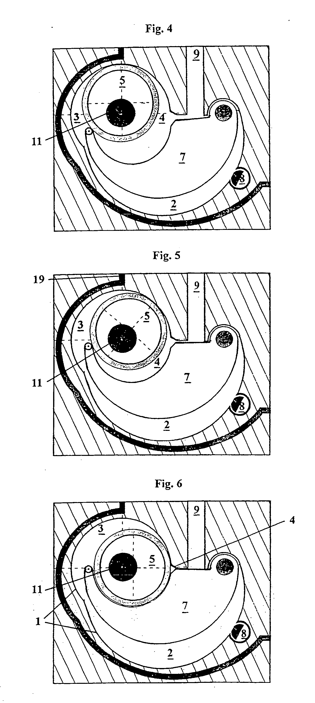
[0026] First of all, a general description is given of an engine according to the invention, which will follow, for example, FIG. 3 and, in exceptional cases, other figures too.

[0027] The simplest embodiment of an engine according to the invention inclues, to use conventional engine terminology, an engine block, which is shown generally in the figures as a shaded area, without ...


PUM


Abstract

A machine, such as an engine, which includes a cylinder (1), an essentially cylindrical piston (5) set on bearings and equipped with an eccentrically-set shaft (11), an inlet port or valve (8), an outlet port or valve (9), and a lever device (7), which is attached by bearings to a shaft (6) and which is intended to be in essentially tight contact with the piston (5). The cylinder (1) forms an essentially cylindrical chamber for the rotary piston (5) and a partially cylindrical chamber for the lever device (7) that moves backwards and forwards. The piston (5) is equipped, in the interior of the working chamber, with sliding-ring-type bearings (13, 14).

Description

CROSS-REFERENCE TO RELATED APPLICATIONS, IF ANY [0001] This application is a continuation of U.S. patent application Ser. No. 09 / 869,740, filed Jul. 3, 2001, which is hereby incorporated by reference.STATEMENT REGARDING FEDERALLY SPONSORED RESEARCH OR DEVELOPMENT [0002] Not applicable. REFERENCE TO A MICROFICHE APPENDIX, IF ANY [0003] Not applicable. FIELD OF INVENTION [0004] The present invention relates to a lever-mechanism engine, and specifically to a lever-mechanism engine or pump, which, in the following, will be generally referred to as a lever-piston engine. The engine is of a type that has two separately operating pistons. The operation of the engine is based on the thermal expansion or contraction of a medium. The operation may be based on a closed and / or open thermodynamic principle, and in general on exploiting the pressure of a medium. SUMMARY OF THE INVENTION [0005] Engines coming within the scope of the invention are, in terms of their operating principle, usually eng...

Claims


Application Information

Patent Timeline
IPC IPC(8): F01C1/39F01C11/00F01C19/02F01C1/46F01C20/00F01C21/02F01C21/06F01C21/08F01C21/10F01C21/18F02B53/00F03C4/00
CPCF01C1/39F02B53/00F01C11/002F01C9/00
Inventor RANTALA, VEIKKO KALEVI
Owner RANTALA VEIKKO KALEVI
Learn More