Piston having a patterned coating and method of applying same

a technology of patterned coating and piston, which is applied in the direction of machines/engines, manufacturing tools, mechanical equipment, etc., can solve the problems of engine seizing or failing, scuffing on the surface of either the piston skirt or the cylinder, etc., and achieves improved directing properties, cost-effective

Active Publication Date: 2005-04-28
MAHLE TECH
View PDF10 Cites 58 Cited by
  • Summary
  • Abstract
  • Description
  • Claims
  • Application Information

AI Technical Summary

Benefits of technology

[0011] Accordingly, one advantage of the present invention is that it provides a piston having improved properties for retaining lubrication between the piston skirt and cylinder wall during operation of an internal combustion engine.
[0012] Another advantage of the present invention is that the piston has improved properties for directing the flow of lubrication between the piston skirt and cylinder wall during operation of an internal combustion engine.
[0013] Another advantage of the present invention is that it provides a lubrication enhancing piston skirt having a coating bonded specifically to the thrust sides of a piston skirt, where lubrication is most necessary.
[0014] Yet another advantage of the present invention is that it provides a lubrication enhancing piston skirt having a coating bonded to each thrust side in a predetermined pattern for specific lubrication flow direction and / or retention relative to the movement of a piston within a cylinder.
[0015] Still another advantage present invention is that it provides a cost-effective method of applying a lubrication-enhancing coating to a piston skirt by using an improved manufacturing process that eliminates the step of micro-grooving the piston prior to applying the coating.

Problems solved by technology

While lubricant (i.e. oil) generally prevents metal-to-metal contact between the piston skirt and the cylinder wall, factors such a load, temperature and insufficient lubrication may reduce or eliminate the layer of lubricant and cause scuffing on the surface of either the piston skirt or the cylinder or both.
Scuffing in this area can ultimately cause the engine to seize or fail.

Method used


Image

  • Piston having a patterned coating and method of applying same
  • Piston having a patterned coating and method of applying same
  • Piston having a patterned coating and method of applying same

Examples


Embodiment Construction

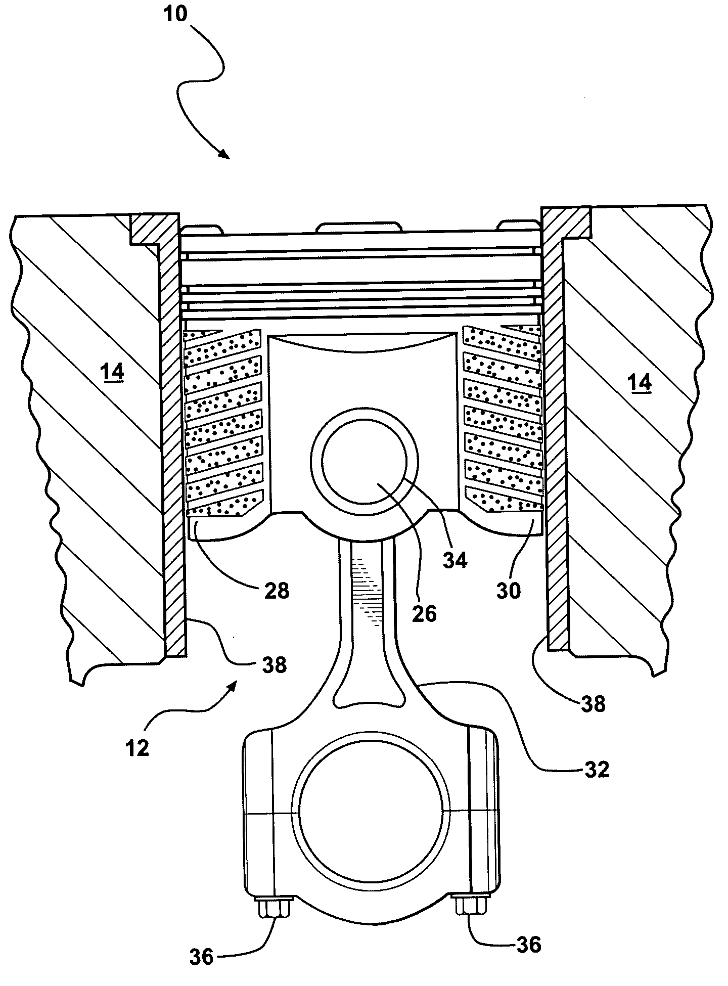
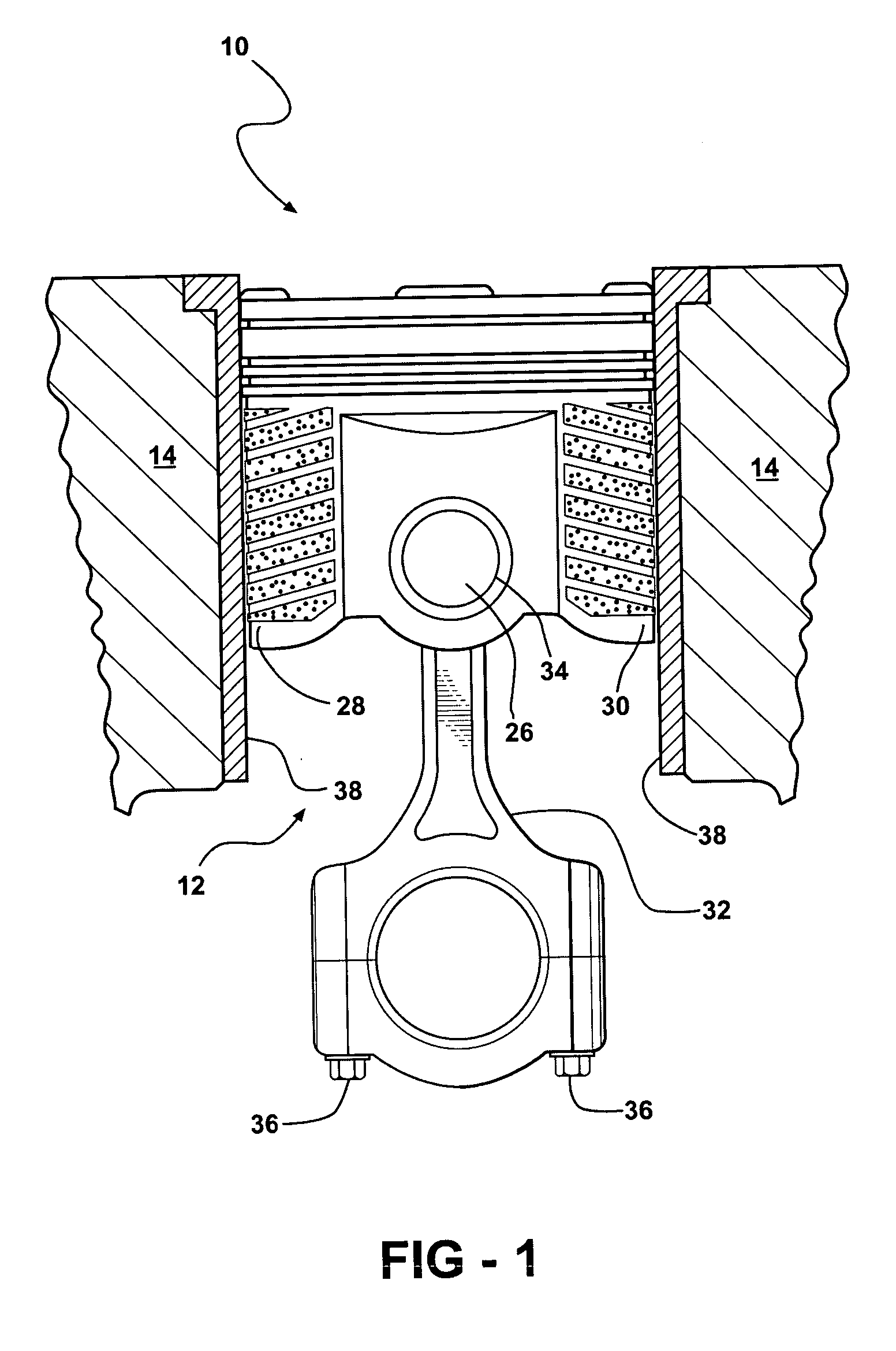
[0028] The present invention overcomes the disadvantages in the related art in a coated piston, generally indicated at 10, 110, 210, 310, 410, 510, 610 and 710 in the figures, where like numbers are used to designate like structure throughout the drawings. As best shown in FIG. 1, one embodiment of the piston of the present invention is generally indicated at 10. The piston 10 is adapted for reciprocal movement within a cylinder 12 of an internal combustion engine 14. As best shown in FIG. 2, the piston 10 includes a body 16 having a crown 18 formed at the uppermost margins of the body 16 and a skirt 20 depending from the crown 18. The piston 10 further includes ring lands 22 extending about the circumference of the body 16 and adapted to retain piston rings (not shown, but generally known in the art). A pin bore 24 extends through the lower margins of the body 16 and is adapted to receive a piston pin 26.

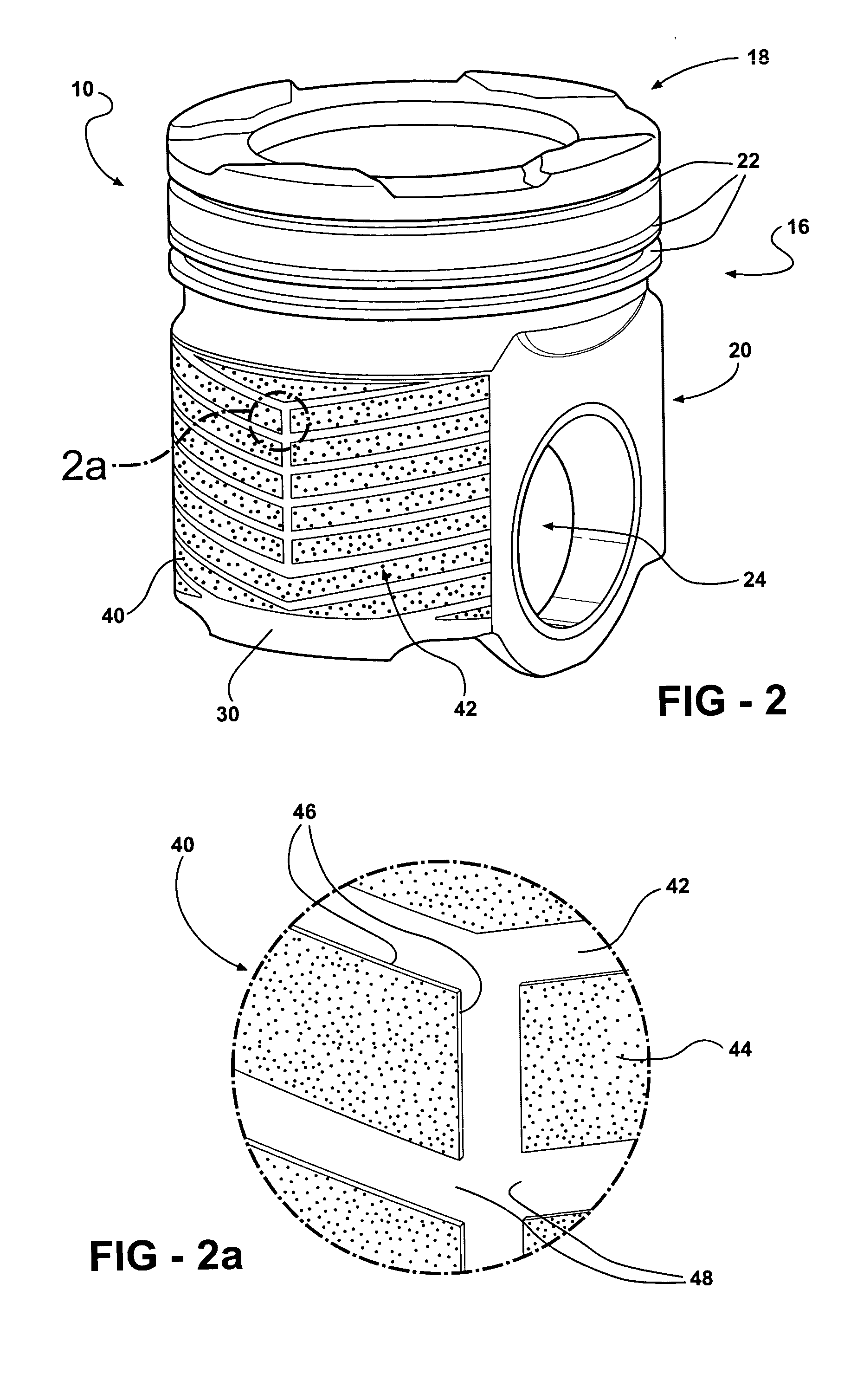
[0029] With reference to FIGS. 1-3, the piston skirt 20 includes an outer cir...


PUM

PropertyMeasurementUnit
thicknessaaaaaaaaaa
thicknessaaaaaaaaaa
circumferenceaaaaaaaaaa

Abstract

The present invention relates to a piston adapted for reciprocal movement within the cylinders of an internal combustion engine. The piston includes a body having a crown formed at the uppermost margins of the body and a skirt, depending from the crown, adapted for relative sliding motion with respect to the cylinder. The piston further includes a coating bonded to the piston skirt so as to be juxtaposed between the skirt and the cylinder. The coating has a plurality of recesses formed thereon so as to define a predetermined pattern of recesses on the surface of the skirt that retains lubricant between the skirt and the cylinder wall. The coating may also direct lubricant along the outer circumference of the piston skirt during reciprocal movement of the piston within a cylinder. A method of applying the coating to the piston skirt is also disclosed.

Description

BACKGROUND OF THE INVENTION [0001] 1. Field of the Invention [0002] The present invention relates, generally, to pistons for internal combustion engines. More specifically, the present invention relates to a piston having a patterned coating applied to the piston skirt for directional lubrication flow and / or lubrication retention as well as a method for applying the coating to the piston. [0003] 2. Description of the Related Art [0004] Internal combustion engines known in the related art may generally include, among other basic components, an engine block having one or more cylinders, cylinder heads associated with the engine block and pistons supported for reciprocal movement in each cylinder. The piston generally includes a body having a crown and a skirt that depends from the crown to define the bottom half of the body of the piston. The bottom half is referred to as a skirt because it “skirts” or surrounds a pin bore formed in the body. The pin bore corresponds to a similar bore...

Claims


Application Information

Patent Timeline
Patent Type & Authority Applications(United States)
IPC IPC(8): C23C4/16C23C30/00F02F3/10F16J1/02
CPCC23C4/16C23C30/00Y10T29/49263F16J1/02F02F3/105
Inventor REIN, WOLFGANGROTH, DAVIDDOUGLAS, JONATHAN
Owner MAHLE TECH
Why Eureka
Try Eureka