
Optimized photodiode process for improved transfer gate leakage

a photodiode and process technology, applied in the field of improved photodiodes, can solve the problems of significant drawbacks of conventional cmos image devices, and achieve the effects of reducing leakage, improving photodiode implant performance, and good charge transfer characteristics

Active Publication Date: 2005-04-28
APTINA IMAGING CORP
View PDF25 Cites 16 Cited by
  • Summary
  • Abstract
  • Description
  • Claims
  • Application Information

AI Technical Summary

Benefits of technology

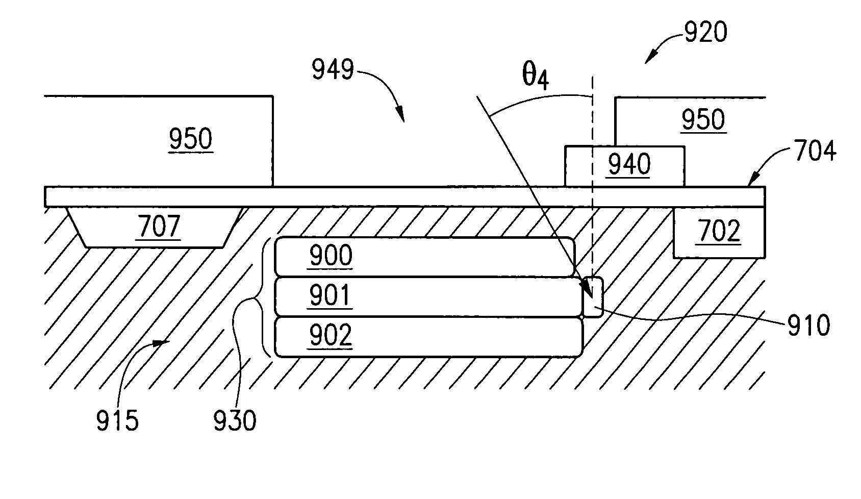
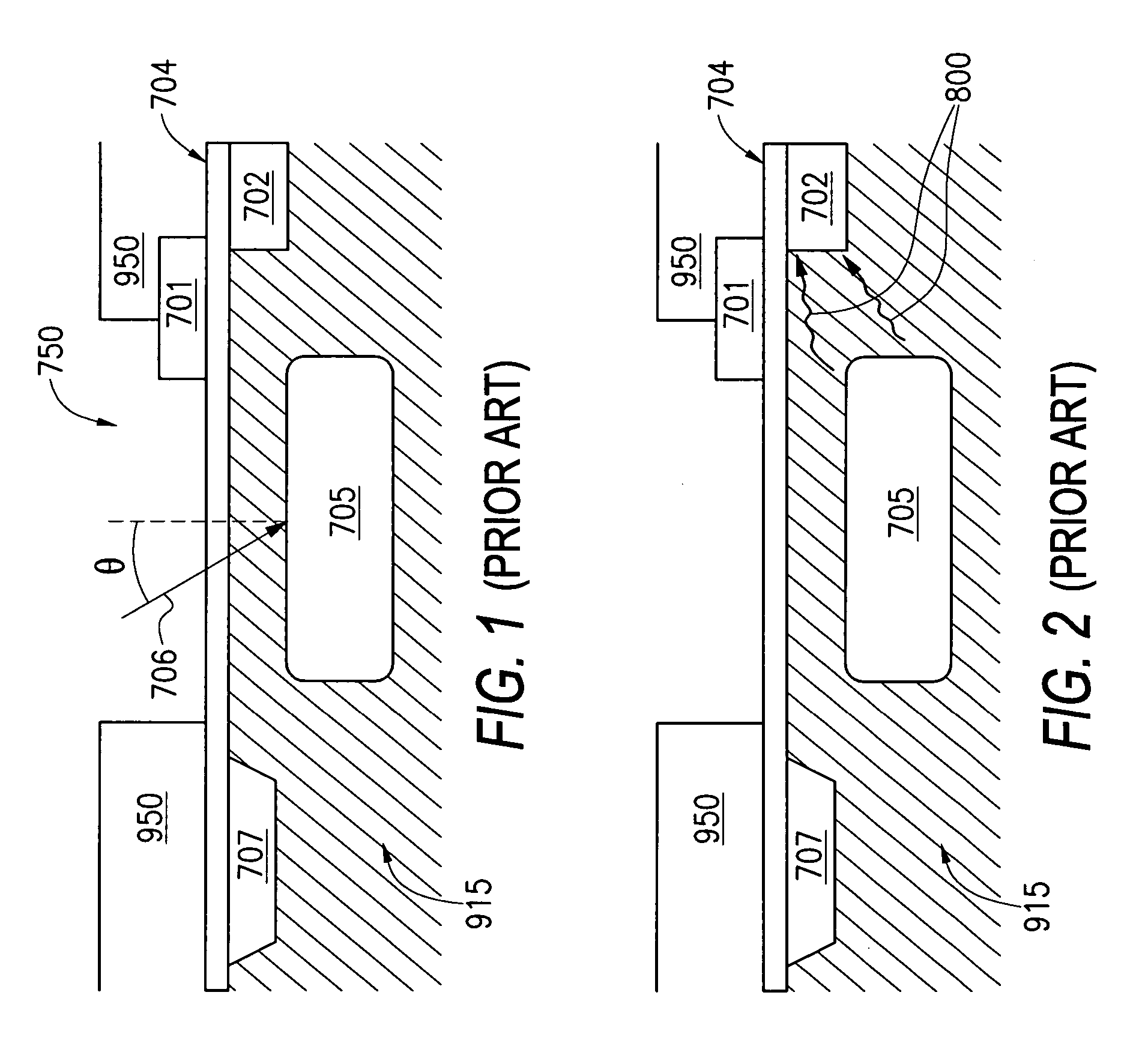
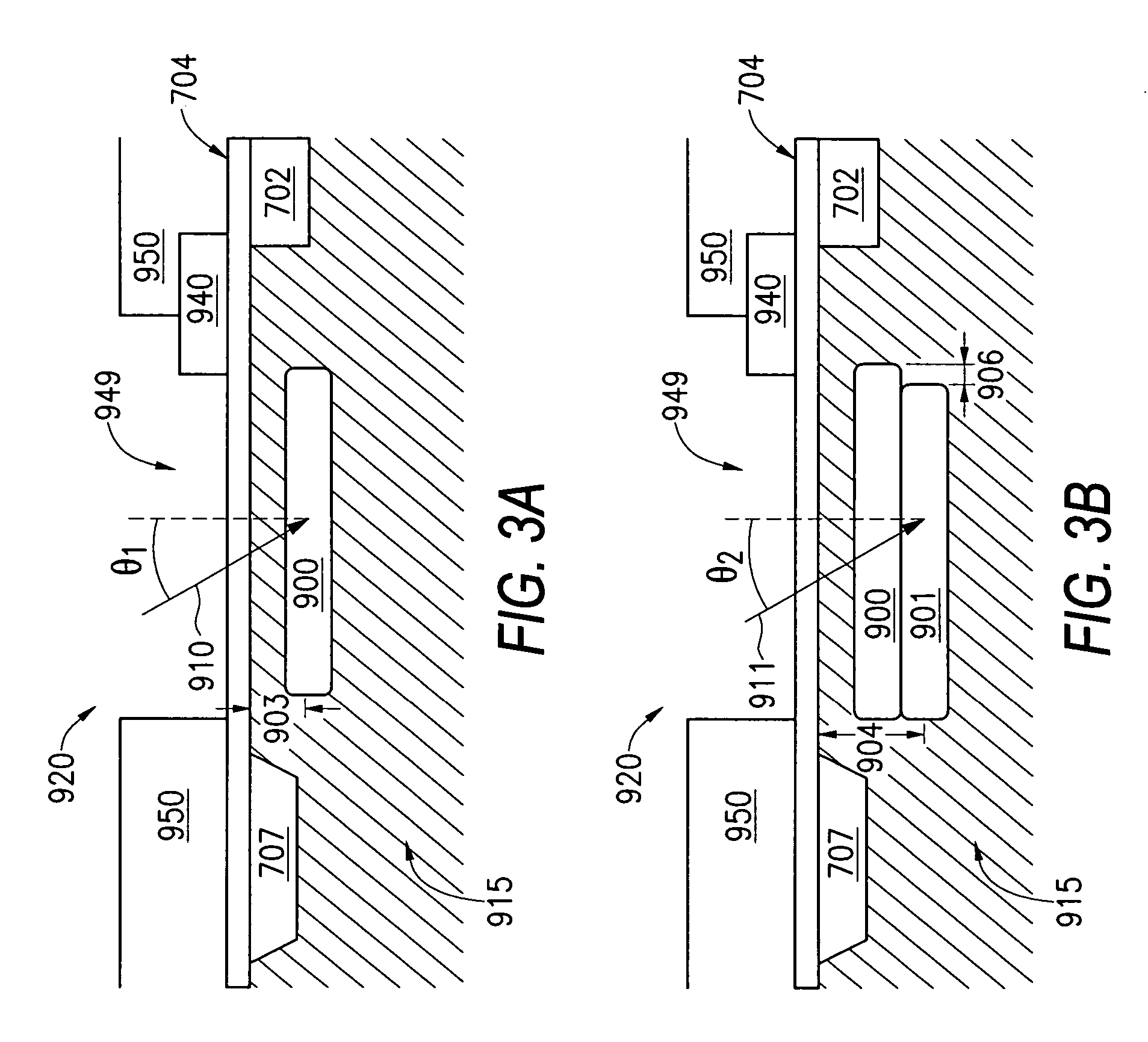
[0005] The present invention provides a CMOS imager having a pixel array in which each pixel has an improved photodiode implant. The photodiode implant is created by tailoring the angle of a plurality of charge collection region implants so that the resulting charge collection region is positioned to provide a good charge transfer characteristic when the transfer transistor gate is on and lowered leakage across the channel region when the transistor gate is off. The photodiode charge collection region is formed through the successive implants into the substrate, some of which are angled, to minimize the barrier and in turn minimize the leakage.

Problems solved by technology

However, conventional CMOS image devices have some significant drawbacks.

Method used


Image

  • Optimized photodiode process for improved transfer gate leakage
  • Optimized photodiode process for improved transfer gate leakage
  • Optimized photodiode process for improved transfer gate leakage

Examples


Embodiment Construction

[0019] In the following detailed description, reference is made to the accompanying drawings which form a part hereof, and in which is shown by way of illustration specific embodiments in which the invention may be practiced. These embodiments are described in sufficient detail to enable those skilled in the art to practice the invention, and it is to be understood that other embodiments may be utilized, and that structural, logical and electrical changes may be made without departing from the spirit and scope of the present invention.

[0020] The terms “wafer” and “substrate” are to be understood as including silicon, silicon-on-insulator (SOI) or silicon-on-sapphire (SOS) technology, doped and undoped semiconductors, epitaxial layers of silicon supported by a base semiconductor foundation, and other semiconductor structures. In addition, the semiconductor need not be silicon-based, but could be based on silicon-germanium, germanium, or gallium arsenide. Furthermore, when reference ...


PUM


Abstract

An image sensing circuit and method is disclosed, wherein a photodiode is formed in a substrate through a series of angled implants. The photodiode is formed by a first, second and third implant, wherein at least one of the implants are angled so as to allow the resulting photodiode to extend out beneath an adjoining gate. Under an alternate embodiment, a fourth implant is added, under an increased implant angle, in the region of the second implant. The resulting photodiode structure substantially reduces or eliminates transfer gate subthreshold leakage.

Description

FIELD OF THE INVENTION [0001] The present invention relates to improved photodiodes used in pixels of an image array. BACKGROUND OF THE INVENTION [0002] CMOS image devices having pixel sensor arrays are well known in the art and have been widely used due to their low voltage operation and low power consumption. CMOS image devices further have advantages of being compatible with integrated on-chip electronics, allowing random access to the image data, and having lower fabrication costs as compared to other imaging technologies. CMOS image devices are generally disclosed for example, in Nixon et al., “256×256 CMOS Active Pixel Sensor Camera-on-a-Chip,” IEEE Journal of Solid State Circuits, vol. 31(12) pp. 2046-2050, 1996; Mendis et al., CMOS Active Pixel Image Sensors,” IEEE Transactions on Electron Devices, vol. 41(3) pp. 452-453, 1994 as well as U.S. Pat. Nos. 5,708,263, 5,471,515, and 6,291,280, which are hereby incorporated by reference. [0003] However, conventional CMOS image dev...

Claims


Application Information

Patent Timeline
Patent Type & Authority Applications(United States)
IPC IPC(8): H01L21/00H01L27/146H01L31/0352H01L31/062H01L31/103
CPCH01L27/14601H01L27/14643Y02E10/50H01L31/103H01L31/03529Y02E10/547
Inventor RHODES, HOWARD E.MAURITZSON, RICHARD A.PATRICK, INNA
Owner APTINA IMAGING CORP
Learn More