
Power control device for vehicle

a technology for power control devices and vehicles, applied in the direction of electric generator control, engine starters, instruments, etc., can solve the problems of difficult regeneration or electrical generation, and the time which is needed for the driver to move his/her vehicle to a safe place is restricted to a very short time, so as to achieve high reliability

Active Publication Date: 2005-04-28
MITSUBISHI ELECTRIC CORP
View PDF25 Cites 13 Cited by
  • Summary
  • Abstract
  • Description
  • Claims
  • Application Information

AI Technical Summary

Benefits of technology

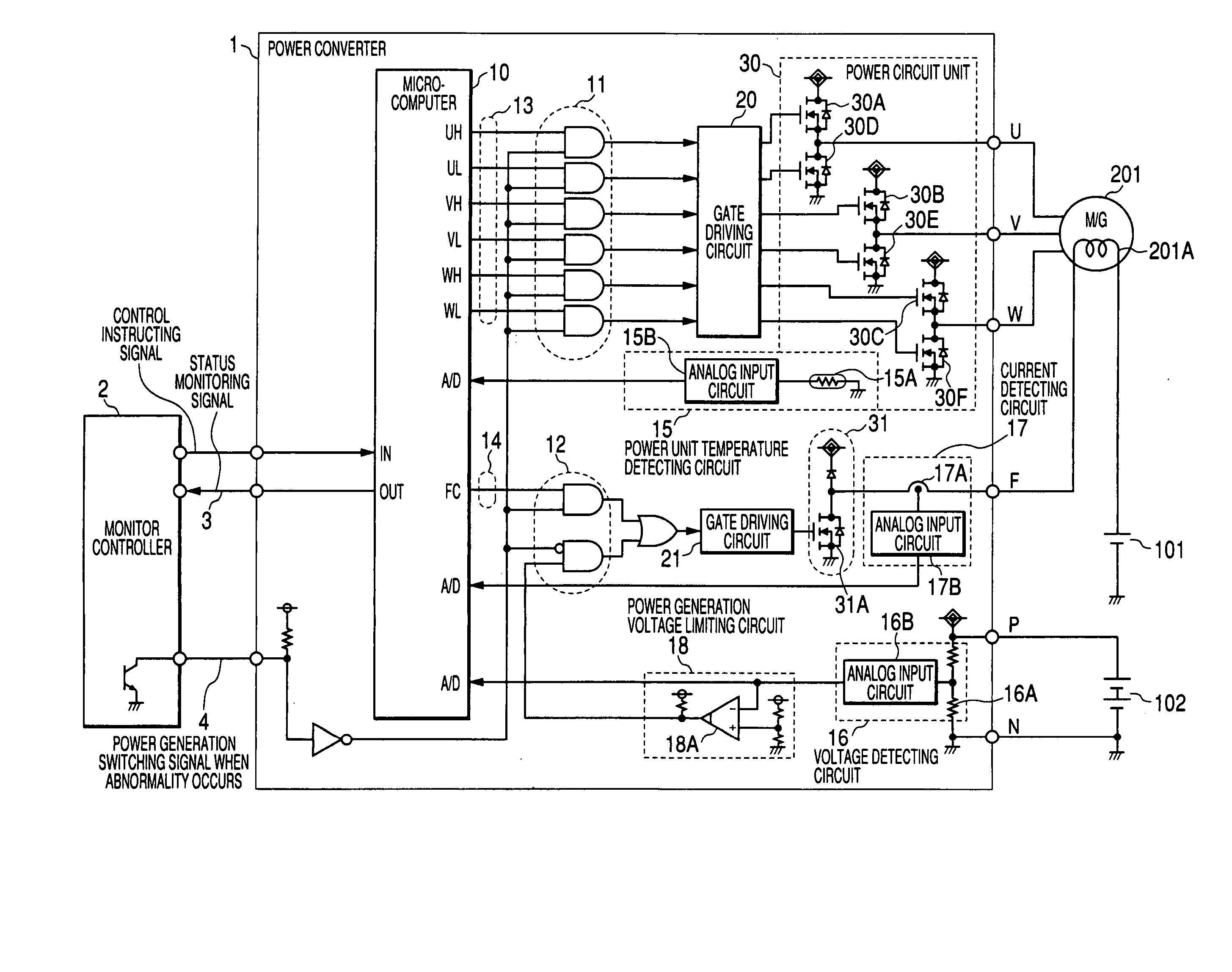
[0010] According to the present invention, at the time when the circuit which is not directly involved in the electric generation control breaks down, for example, at the time when abnormality of a microcomputer occurs or at the time when an interface circuit between a power converter and a monitoring control device breaks down, the breakdown is detected and an alarm is emitted to a driver, and also sufficient power needed for continuous traveling can be supplied without stopping the electric generation which is the main function of the power converter, so that there can be provided a vehicle power control device having high reliability.

Problems solved by technology

Accordingly, when the power element driving signal generating means of the power converter does not normally function due to breakdown or the like, it is difficult to perform regeneration or electrical generation.
Furthermore, when the charging to the battery is suddenly stopped, the time which is needed for the driver to move his / her vehicle to a safe place is restricted to a very short time.
Conversely, when the current supply of the field coil cannot be stopped, over-excitation occurs, so that a critical defect such as overcharge of the battery or the like as a power source system for a vehicle may be caused.

Method used


Image

  • Power control device for vehicle
  • Power control device for vehicle
  • Power control device for vehicle

Examples


first embodiment

[0020] The basic operation of a power converter 1 is the same or similar to the operation of a device which is generally called as an inverter, and thus the description thereof is omitted. In the following description, the function targeted by the present invention will be taken up and described.

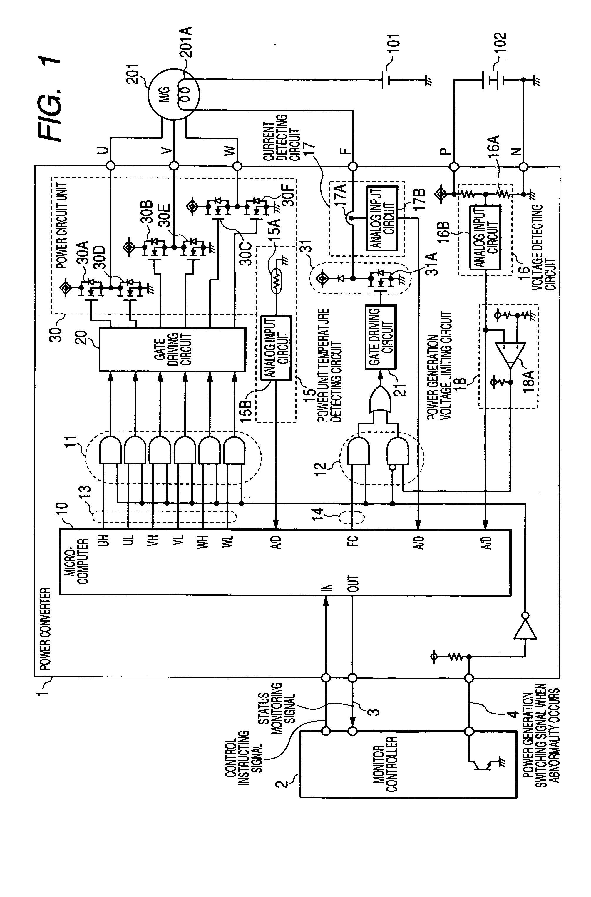
[0021]FIG. 1 is a block diagram showing the circuit construction of a vehicle power control device in a system constituting plural power supply systems on the same vehicle. In this power supply system, a low-voltage battery 101 is a 12V battery for supplying a voltage of 12V, and a high-voltage battery 102 supplies a voltage which is equal to or higher than the voltage of the battery 101. For example, the high-voltage battery 102 is a 36V battery. M / G 201 connected to an engine is designed in a field coil type, current to be supplied to the field coil 201A for excitation is supplied from the low-voltage battery 101, and power regenerated by the power converter 1 for controlling the driving ...

second embodiment

[0030] In this embodiment, a field current limiting circuit 40 containing a comparator 40A is added to the output side of the current detecting circuit 17 as shown in FIG. 4, and even when the voltage detected by the voltage detecting circuit 16 described above is lower than a predetermined value, the field coil driving circuit 31 is set to OFF if the current value detected by the current detecting circuit 17 is not less than a predetermined value. This embodiment is effective to such a case that when a predetermined current value or more is supplied under some surrounding temperature environment, the field coil driving circuit 31 may be burned out on the field coil design aiming at the enhancement of the output performance of M / G.

third embodiment

[0031] In this embodiment, a temperature limiting circuit 50 containing a comparator 50A is added to the output side of the power unit temperature detecting circuit 15 as shown in FIG. 5. Even when the voltage detected by the voltage detecting circuit 16 is lower than a predetermined value and the current value detected by the current detecting circuit 17 is not more than a predetermined value, the field coil driving circuit 31 is set to OFF if the power unit temperature fed back from the power unit temperature detecting circuit 15 is not less than a predetermined value. Accordingly, the field coil current can be limited when the second electric generation control function is executed by inputting to the temperature limiting circuit 50 the detection signal of the power unit temperature detecting circuit 15 which detects the temperature of an existing power element or surrounding temperature with which the temperature of the existing power element can be estimated.


PUM


Abstract

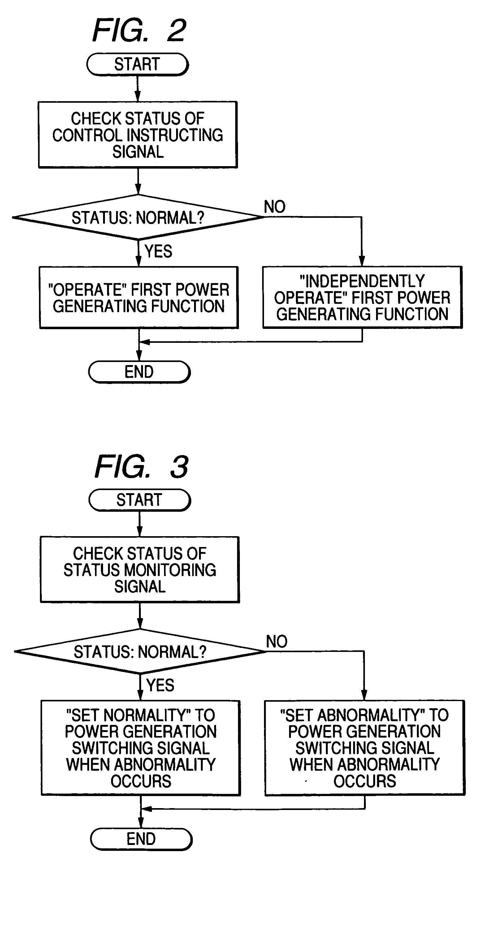
In a power control device for a vehicle, a monitoring control device 2 disposed separately from a power converter 1 judges normality / abnormality of the power converter 1, and sets an abnormality-occurrence electric generation switching signal 4 to ON / OFF, whereby a first electric generation control function corresponding to an output of power element driving signal generating means is forcedly stopped, and also a second electric generation control function based on a diode rectifying mode of a power element is started.

Description

BACKGROUND OF THE INVENTION [0001] 1. Field of the Invention [0002] The present invention relates to a vehicle power control device mounted in an electrical vehicle or the like, particularly to a vehicle power control-device in which the ordinary electric generation function can be switched to the auxiliary electric generation function when abnormality occurs. [0003] 2. Description of the Related Art [0004] In an electric powered vehicle such as an electric car or a hybrid car, a motor generator (hereinafter referred to as “M / G”) is equipped in place of a conventional diode rectification type electric generator for the high value-added purpose such as driving / braking of a vehicle, starting of a motor and an internal combustion engine mounted on the vehicle, or electric generation for charging a battery, and a power converter (popularly named as inverter) for M / G driving control. A microcomputer, a dedicated LSI or the like is used as means for generating a power element driving sign...

Claims


Application Information

Patent Timeline
IPC IPC(8): B60L3/00B60L11/00F02N11/04G08B21/00G21D7/02H02H7/00H02J7/14H02K44/00H02P9/30
CPCH02P9/305H02P2101/45H02P29/022H02P29/032
Inventor MATSUOKA, SYOUGO
Owner MITSUBISHI ELECTRIC CORP
Learn More